80
1 1 5 0 / 1 1 5 5 H A Y B U S T E R T U B G R I N D E R O P E R A T I N G I N S T R U C T I O N S
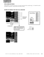
ELECTRONIC GOVERNOR HARDWARE TEST (FOR S.N. 0167 AND UP)
NOTE:
1150/1155 HAYBUSTER TUB GRINDERS S.N. 0167 AND UP contain 24 volt systems.
1. Power source: 24 volts DC
Red wire + positive pin A wiring harness
Black wire ‑ Negative Pin B wiring harness
2. Test output voltage to valve DC
Red wire + positive pin D wiring harness.
Black wire - negative pin E. wiring harness.
Test the electronic governor with power supplied to the governor control box and the mode switch set to the tub
position. The grinder does not need to be running for this test. Disconnect the wiring harness at the valve. With a
voltmeter set for 24 volts DC, connect the red lead of the voltmeter to the red lead of the wiring harness and black
lead to the black wire. Turn the tub limit knob until the left speed light (turtle) is on. The voltmeter should read
approximately 6 volts. Turn the tub limit knob clockwise. As more speed lights light up, the voltage should increase.
Turn the knob until the right speed light (Rabbit) is lit. The volt meter should now read a minimum of 18 volts.
3. Output voltage of sensor AC
red wire - Pin C wiring harness
Black wire - Pin B wiring harness.
Set the sensor gap to 3/32”.
Remove the wiring harness from the electronic governor.
With the engine at operating temperature and the clutch engaged, throttle the engine up to the desired engine RPM.
With volt meter set to AC volts, connect leads to pins B and C. The volt meter should read 2 to 3 volts AC .


