6
Notice
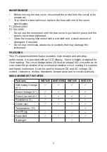
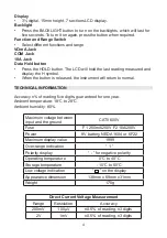
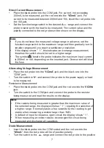
• If you do not know the measured voltage range in advance, set the
function/range switch to the maxium range and then gradually turn to
smaller ranges until you reach a satisfactory resolution.
• If the display shows “ 1 ”, this indicates an overrange measurement,
therefore the switch should be set to a higher range.
• Do not input a voltage of more than 600V. It is capable of indicating a
higher voltage, but with the risk of damaging the inside circuit.
• When taking the measurement of high voltage, pay special attention to
avoid an electric shock.
Direct Voltage Measurement
• Insert the red probe into the “
VΩmA
” jack and the black one into the COM
jack.
• Turn the function/range switch to the range of
V
and connect the probe
to the power supply or load to be measured. The polarity touched by the
red probe will be on the display.
• Plug the instrument in and check the 9V battery. If it is low the “ ”
symbol will display, meaning the battery needs replacing.
• The besides the probe jack indicates that the input voltage or current
should not exceed the specified limits, in orderto protect the internal
circuit.
• Before measurement, turn the function/range switch to the desired range.
+ -
!
OPERATION
•
Overload protection: 250V DC or RMS. AC.
Temperature Measurement
Range Resolution
Measurement
Accuracy
°C
1°C
-20°C to 0°C
-0°C to 400°C
400°C to 1000°C
±10% Range, ±2 digits
±1.0% Range, ±3 digits
±2.0% Range
Diode and Circuit On-Off Measurement
Range
Description
When the on-resistance is smaller than (70±30)
Ω, the
built-in buzzer will sound.
Displays the approximate diode postive voltage.


