10
•
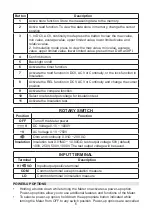
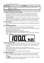
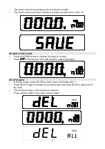
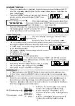
After performing the insulation test, press SELECT to view DAR or PI.
•
If DAR or PI are invalid, the meter will display “- - - -”.
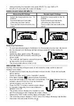
Measuring DC Voltage
Measuring AC Voltage
•
Switch the rotary switch to the
V
position.
•
Input terminals and test leads,
connecting as shown below.
•
Then connect the test leads to the
circuit.
•
Switch the rotary switch to the
~V
position.
•
Input terminals and test leads,
connecting as shown below.
•
Then connect the test leads to the
circuit.
MAKING BASIC MEASUREMENTS
Measuring Resistance
•
To avoid possible damage to the Meter or to the equipment under test, disconnect
the circuit power and discharge all high voltage capacitors before testing for
continuity.
•
Switch the rotary switch to the position.
•
Input terminals and test leads, connecting as
shown (right).
•
The continuity test features a beep that sounds
as long as the circuit is complete.
•
The beep sounds when a short (<3 Ω).
INSULATION TEST
Warning: When testing voltage output, do not rotate the rotary switch to prevent
damage to the Meter.
•
Insulation tests should only be performed on dead circuits. Check the test leads
before testing.
•
Switch the rotary switch to the “Insulation” position.
•
If the Meter displays , please replace the battery.
•
Insert the test leads to the High and Low terminals. If the Meter displays the Live
indicator, power off the Live circuit as the Meter
cannot measure on a live circuit.
•
Press the TEST.V button to select output voltage.
•
In insulation measuring the screen alternates
between on or off.
•
The primary screen displays the resistance value
and the secondary screen displays the output voltage.
•
Release the TEST button and the Meter will display “DISC”.
•
The secondary screen displays “0 VDC” when the voltage discharge has finished.
•
Disconnect the test leads from the circuit.


