5
5
12
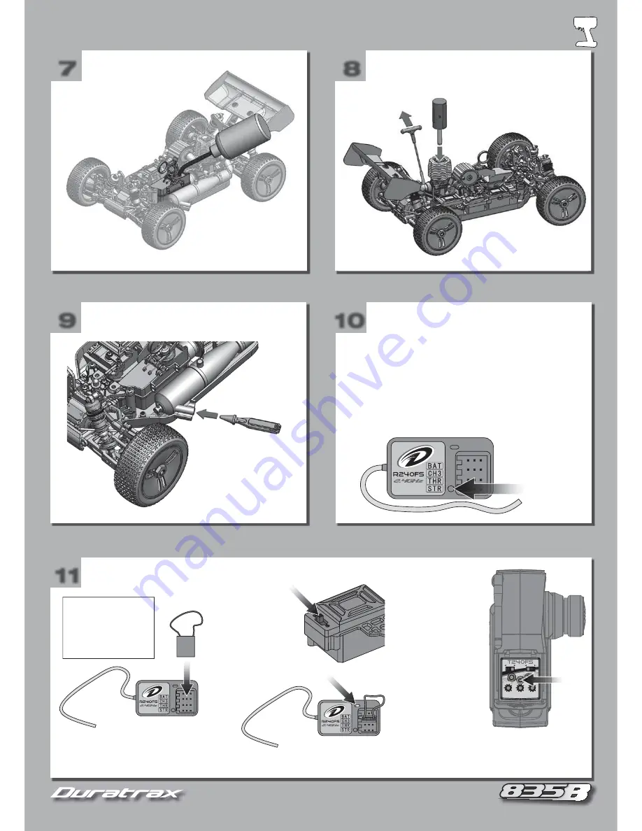
STOP THE ENGINE
7
7
8
8
5
5
FUEL THE CAR
START THE ENGINE
10
10
9
9
STOP THE ENGINE
FAILSAFE
N
R
ST
N
R
TH
BIND
ST-D/R
TH-TRIM
ST-TRIM
11
11
RE-BIND THE TRANSMITTER TO THE RECEIVER
See page 6 for starting
and engine break-in.
To stop your 835b engine,
place the pointed end of
the engine tool into the
exhaust outlet (stinger).
This will block the exhaust
and stop the engine.
Your radio system is
preset at the factory.
If you need to re-bind
your system, follow
these steps.
1. Insert bind plug into
receiver channel 3.
2. Move the radio
box switch to the
“ON” position.
The LED should
start blinking.
4. Move the radio box switch to the “OFF”
position and turn off the transmitter.
Remove the bind plug from the receiver.
3. Hold down the
transmitter’s “bind”
button and turn on
the transmitter. The
receiver LED will
stop blinking
To set:
1. Power up the transmitter and receiver.
2. Hold the buggy so the wheels are off the ground and clear
of all objects.
3. With the transmitter throttle in neutral, press the failsafe set
button on the receiver. The receiver LED will fl ash to indicate
a new failsafe point
has been set.
The R240FS receiver has a build in failsafe. If the
receiver loses contact with the transmitter, it will
automatically return the throttle to a preset point.
Failsafe Set
Button
Summary of Contents for 835B
Page 1: ... ...
Page 11: ...11 11 FOR MAINTENANCE AND REPAIRS ON YOUR 835B FOR MAINTENANCE AND REPAIRS ON YOUR 835B ...
Page 16: ...16 16 16 16 14 14 15 15 CC x2 4x12mm 169 x2 HH x2 3mm 13 13 152 x2 3x40mm 19 x2 5x30mm ...
Page 18: ...18 18 20 20 21 21 Z x2 3x3mm 149 x2 D x2 3x8mm 19 19 J x2 3x18mm ...
Page 20: ...20 20 26 26 27 27 X x2 3x20mm E x1 3x10mm 25 25 Y x2 3x30mm ...
Page 23: ...23 23 23 23 35 35 36 36 F x6 3x12mm M x2 4x20mm 34 34 AA x2 3x10mm 158 x2 REAR x2 ...
Page 24: ...24 24 38 38 39 39 Z x2 3x3mm 149 x2 J x2 3x18mm D x2 3x8mm 37 37 ...
Page 25: ...25 25 41 41 42 42 HH x1 3mm DD x2 3x8mm HH x2 3mm C x4 6x10mm 40 40 153 x1 3x45mm ...
Page 26: ...26 26 44 44 45 45 T x2 4x12mm 159 x4 U x2 4x14mm 43 43 62 x2 4x45mm ...
Page 27: ...27 27 47 47 48 48 H x4 3x16mm HH x4 3mm U x2 4x14mm Q x6 3x10mm 46 46 ...
Page 29: ...29 29 53 53 54 54 G x4 3x15mm F x4 3x12mm Z x1 3x3mm 52 52 ...
Page 30: ...30 30 Z x1 3x3mm 56 56 57 57 DD x2 3x8mm HH x2 3mm U x4 4x14mm 55 55 ...
Page 31: ...31 31 59 59 60 60 158 x4 3mm 58 58 ...
Page 32: ...32 32 DD x2 3x8mm HH x2 3mm K x2 3x22mm DD x2 3x8mm HH x2 3mm K x2 3x22mm 62 62 63 63 61 61 ...
Page 34: ...34 34 68 68 69 69 L x1 4x12mm 67 67 ...
Page 35: ...35 35 71 71 72 72 F x2 3x12mm Q x2 3x10mm T x1 4x12mm JJ x4 4mm 70 70 ...
Page 36: ...36 36 74 74 75 75 BB x1 4x5mm MM x4 4x10mm F x8 3x12mm 73 73 T x1 4x12mm BB x1 4x5mm ...
Page 38: ...38 38 80 80 81 81 F x2 3x12mm N x1 3x8mm HH x4 3mm H x2 3x16mm HH x2 3mm 79 79 Q x6 3x10mm ...


