background image

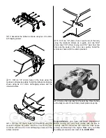
3. Using the provided double-sided tape, attach the radio

receiver  to  the  top  of  the  radio  tray.  To  find  the  top  of  the
radio  tray,  place  the  large  circular  hole  to  the  lower  left  as
shown. Make sure that the receiver is installed in the space
between the sets of screw holes as shown above.

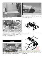
4. Attach the switch from your radio system so it is above

the top of the radio plate (make sure the switch is in the OFF
position). Remove the two screws on the top of the switch.
Place  the  switch  plate  on  top  of  the  radio  tray,  the  switch
body  on  the  bottom  of  the  radio  tray  and  then  reinsert  the
screws from the top.

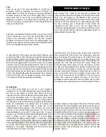
5. Attach the radio tray mounts as shown to the chassis

with (4) 3 x 8mm self-tapping screws.

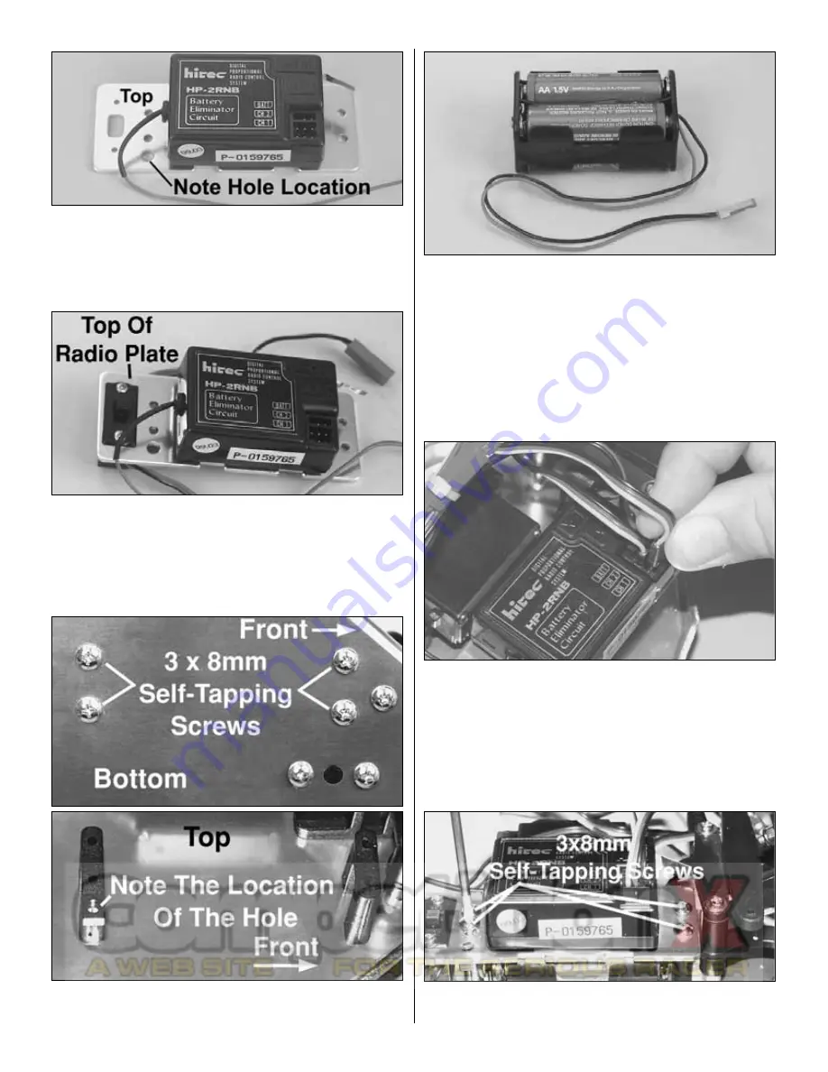
6.  Remove  from  your  radio  system  the  4-cell  receiver

battery  holder  and  install  (4)  “AA”  batteries  (not  included).
The  negative  sides  of  the  batteries  are  placed  against  the
springs  in  the  battery  holder.  Plug  the  connector  on  the
receiver battery holder into the connector on the switch. Make
sure  the  switch  is  in  the  OFF  position.  Place  the  receiver
battery holder between the radio plate posts.

7. Plug the steering servo, throttle servo, and switch into

the receiver. See your radio instructions to determine which
channel  is  steering  and  which  channel  is  throttle.  The
receiver  switch  plugs  into  the  socket  labeled  “Battery,”
“Batt,” or “B.”

8. Attach  the  radio  tray  to  the  radio  tray  posts  with  (4) 

3 x 8mm self-tapping screws.

9

Summary of Contents for MAXIMUM MT

Page 1: ...es 1610 Interstate Drive Champaign Illinois 61822 Attn Service Department Phone 217 398 0007 9 00 am 5 00 pm Central Time M F E mail hobbyservices hobbico com Before Building We want the building and operating of this vehicle to be a success so BEFORE removing any parts from the parts bags please read this manual thoroughly and watch the included video to familiarize yourself with the model If for...

Page 2: ...low all of the precautions on the fuel container Keep fuel out of the reach of children Model engine fuel is flammable and when ignited has a flame that is difficult to see Avoid sparks flames smoking or any other ignition source when fuel is near The engine emits carbon dioxide just like real cars Do not operate this model indoors Before turning on the transmitter make sure that no one else is on...

Page 3: ...ews Do not use thread locking compound on any self tapping screws The thread locking compound may damage the plastic IMPORTANT Use thread lock on any fastener that is threaded into metal or fastened with a nut Vibration from the engine will cause the screws to loosen if thread locking compound is not used The illustration above shows how to identify the types of screws used throughout this instruc...

Page 4: ...ace a 1 8 long piece of fuel tubing over the antenna tube and wire to secure in place TIP Run the antenna through your fingers to straighten out kinks before running through the antenna tube 4 Remove the air filter and tie strap from the parts bag Thoroughly soak the air filter foam with some oil not included and then squeeze out the excess oil A light machine oil like 3 IN ONE will work well Spec...

Page 5: ...smitter battery holder Place 8 AA batteries into the holder in the configuration molded into the plastic on the battery holder Re install the transmitter battery holder into the transmitter and re install the battery door 10 Turn on the transmitter using the switch on the back see the photo with Step 8 The green light on the side of the transmitter should light up If there is no light on turn the ...

Page 6: ...uded 15 Drill one 1 8 3mm hole in each side of the body using the molded in dimple as a guide and one 5 64 2mm hole 7 16 11mm below and 7 16 back from first hole use the pegs on the mirror as a guide Install the mirrors as shown with the collars provided 16 Remove the body clips from the parts bag Place the body on the body mounts On each body mount place a body clip Congratulations you have compl...

Page 7: ...rax Maximum MT read the manufacturer s instructions manual and follow the instructions shown below Servo Arm Steering Servo Throttle Servo Receiver Battery Holder 4 AA Batteries Transmitter 5 6 1 Antenna 4 8 AA Batteries 1 Receiver 3 Receiver Switch 7 Antenna 2 8 PREPARING THE RADIO SYSTEM ASSEMBLY OF THE PRE BUILT VERSION DTXC0064 Place a check mark in the check boxes after each step is completed...

Page 8: ...onnector must swivel freely Install the 2mm nut onto the bottom of the rod connector Install a 2mm set screw into the top of the rod connector Note When installing the set screw make sure not to thread it in too far because the steering rod must pass through the hole on the side of the rod connector 8 Slip the steering rod through the hole in the rod connector that is already installed on the serv...

Page 9: ...op 5 Attach the radio tray mounts as shown to the chassis with 4 3 x 8mm self tapping screws 6 Remove from your radio system the 4 cell receiver battery holder and install 4 AA batteries not included The negative sides of the batteries are placed against the springs in the battery holder Plug the connector on the receiver battery holder into the connector on the switch Make sure the switch is in t...

Page 10: ...ws to attach the throttle servo and the mounts to the chassis Make sure that the servo spline is towards the rear 1 From bags PA001 and PA003 remove the brake rod the throttle rod the brake spring 3 3 x 3mm set screws the 2mm nut the rod connector and 3 2mm collars 2 From your radio system remove a large X shaped servo arm Remove two of the servo arms as shown Install the rod connector in the last...

Page 11: ...nd another 2mm collar at the end of the throttle rod Place a small amount of thread locking compound on two of the 3 3 x 3mm set screws and thread them into the 2mm collars Do not tighten the set screws all the way In the next section we will make adjustments to the collars Turn on the transmitter first then the receiver Center the trims of the throttle and steering channels see your radio system ...

Page 12: ...uter collar and cut the throttle rod flush with the outer 2mm collar G Move the throttle spring next to the rod connector H Tighten the inner 2mm collar next to the throttle spring without compressing the spring I Attach the throttle servo arm with the screw included with your radio system 1 Remove the fuel tank by taking out the two screws on the bottom of the chassis 2 Remove the fuel line air c...

Page 13: ...place with the tie strap Cut off the excess part of the strap 1 Bundle all of the wires around the receiver together with a tie strap or a twist tie not included in the kit 2 Remove the clear covering from the outside of the body Apply decals to the body if desired For decal placement see the photos on the box top 3 Assemble the rollbar as shown using ten 2 6 x 6mm self tapping screws 4 Drill six ...

Page 14: ...your new truck please take the time to carefully read the instructions and watch the video before running and breaking in the engine Make sure you follow the safety precautions and most of all HAVE FUN The High Speed Needle The high speed needle is sticking up from the side of the carb It is located in the brass housing just above the fuel inlet It controls the fuel to air mixture of the carb The ...

Page 15: ... starting the engine 1 Install a glow plug This threads into the top of the cylinder head 2 Fill the tank Fill the tank almost to the top Leave a little air at the top of the tank 3 Prime the engine Use the primer button on the fuel tank to force the fuel through the fuel line Watch the fuel go through the line and when it gets to the carburetor press the primer button once more to get fuel into t...

Page 16: ...r Engine 1 Keep your engine clean Dirt will act as insulation on an engine It will not be able to shed heat as easily Use a good air filter to keep dirt out of your engine and clean it often 2 Do not over lean your engine 3 Do not run your engine with little or no load Don t throttle up the engine to full throttle when the wheels are not in contact with the ground 4 Do not overheat the engine This...

Page 17: ...If it boils away immediately the high speed needle is set too lean If the water boils away in 3 5 seconds the engine is within proper operating temperatures If the water boils away longer than 5 seconds the mixture is set rich which is preferable when breaking in the engine Otherwise lean the mixture some and retest after a minute of running Ride Height This refers to the clearance between the gro...

Page 18: ...n to race If the rear wheels spin when full power is applied from a stop loosen the nut until the wheels do not spin any more If the wheels do not spin tighten the nut until the wheels spin and then loosen the nut some Before Each Run Check for loosened screws on the truck Engine vibration will loosen some of the screws particularly in the engine mount area Use thread lock on screws that thread in...

Page 19: ... in Try starting the engine again NO NO NO NO YES YES YES YES YES Does the engine quit when the glow plug clip is removed YES YES Clear the engine of fuel NO Reset the high speed needle YES NO Replace the glow plug Check that the pressure line is connected to the muffler The fuel may be bad The engine does not start NO Does the engine turn over easily with the glow plug removed The engine may be f...

Page 20: ...your gear loaded and race ready with the XL field bag Heavy duty black nylon bag with red trim and white logo DTXP2000 DuraTrax Body Repair Tape Need a quick easy fix for Lexan body damage When used with Shoe Goo II fixit compound DTXC2460 the tape s open weave nylon mesh design offers enough flexibility to prevent future cracking DTXR1210 DuraTrax Bearing Completer Set Reduce friction drag and ex...

Reviews: