16
An emergency stop circuit controls electrical power to all parts of the conveyor. When any one
emergency stop switch is activated, power is removed from all motors and actuators stopping all
movement of the conveyor frame and bed. All electrical power is also removed from the motors and
actuators when the DOOR DISCONNECT HANDLE is in the OFF or OPEN positions.
A.
With interlocking door disconnect in the ON position and all Emergency Stop buttons out and
optional Cable Pull switches in the run position, the operator pushes either RESET button. The
MASTER CONTACTOR is energized and the machine is ready to respond to the operator’s
inputs.
B.
Moving the joystick in the DOWN direction starts the traversing motor in the forward direction
after the beeper is sounded for approximately 1.5 seconds , moving the unit toward the dock
door. Releasing the joystick will return it to its centered position, stopping the motor. Moving
the joystick UP starts the traversing motor in the opposite direction after the beeper is sounded.
C.
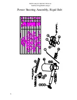
The LEFT and RIGHT positions of the joystick cause the steering actuator to steer the unit. The
unit will steer in the same direction as the joystick movement when the unit is moving forward.
D.
The conveyor bed is controlled by the OFF ON pushbutton. Pressing it once will start the bed
after the beeper is sounded continuously for approximately 1 second. When the bed is running,
pressing this pushbutton turns off the bed.
E.
At any time either Emergency Stop switch may be pushed to de-energize the MASTER contactor. This
will remove power from all motors and actuators. To restart the machine, the Emergency Stop that was
activated must be reset and either RESET pushbutton momentarily depressed. Any motor that was
running prior to the Emergency Stop will have to be restarted through the Operator’s Control Panel.
F.
A feeder control switch provides dry contacts for a customer connection to control the feeder for
the spur or any other function the customer requires.
OPERATING INSTRUCTIONS
PROGRAMMING PACKAGE STOP PHOTOEYES:
Switch on 12” x 12” enclosure on the extension should be in the down position for normal
operation.
To program, flip switch to up position. Cover photoeye for the desired shut off
delay time required on the conveyor belt. There should be a continuous beep for
the time the photoeye is covered during programming.
FMH Conveyors Operator’s Manual
BestReach Rigid Belt Conveyor
Summary of Contents for FMH BestReach
Page 27: ...26 Assembly Rear Suspension FMH Conveyors Operator s Manual BestReach Rigid Belt Conveyor...
Page 28: ...27 Assembly Front Suspension FMH Conveyors Operator s Manual BestReach Rigid Belt Conveyor...
Page 33: ...32 Decal Group Rigid Belt FMH Conveyors Operator s Manual BestReach Rigid Belt Conveyor...
Page 52: ...51 Rigid Belt Schematic STD 480V FMH Conveyors Operator s Manual BestReach Rigid Belt Conveyor...
Page 53: ...52 Rigid Belt Schematic STD 240V FMH Conveyors Operator s Manual BestReach Rigid Belt Conveyor...
Page 60: ...59 Wiring Diagram Limit Switch FMH Conveyors Operator s Manual BestReach Rigid Belt Conveyor...
Page 69: ......


