FMH Conveyors
®
Operator’s Manual
NestaFlex 376PL Conveyors
12 |
P A G E
EFFECTIVE JUNE 2017 PART # 016842 ©2016 FMH CONVEYORS LLC
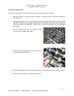
H Frame Replacement
Tools and Parts required: ½” wrenches (2), 5/32” Allen wrench, loctite
242 or equivalent, dimple lock
nuts (6), 5/16‐18 self‐tapping screws (2), nut plates (2), H Frame.
1.
Move the conveyor off the guide track.
2.
Identify the section of conveyor that contains the H Frame to be replaced.
3.
Separate that conveyor section by removing the quick connect fasteners; Retain the fasteners for
the re‐assembly process.
4.
Fully contract the conveyor section.
5.
Carefully lay the conveyor section on its side.
6.
Loosen the two set screws that secure the inner leg/casters.
7.
Remove the inner leg/casters by pulling them out of the H Frame outer legs. Set the inner
leg/casters aside for later use.
8.
On both sides, remove the self‐tapping screw that secures the H Frame to the leg support bracket
and the nut plates; discard the nut plates.
9.
Remove the H Frame.
10.
Insert the new H Frame by sliding it through the square openings in the side guide and then into
the leg support bracket. The screw hole in the H Frame should line up with the hole in the leg
support bracket.
11.
On both sides, position the new nut plate and install the new self‐tapping screw.
12.
Insert the inner leg/casters fully into the H Frame outer legs.
13.
Apply loctite to the set screws and tighten the set screws.
14.
Carefully return the conveyor to an upright position.
15.
Return the conveyor section to its correct location within the conveyor system.
16.
Push the conveyor sections together to align the holes in the quick connect plates.
17.
Insert the top screw on each side and add the washer and nut.
18.
Insert the two remaining screws on each side and add the washers and nuts.
19.
Securely tighten each fastener.
20.
Return the conveyor system onto the guide track.

