background image

Rev.4 

18 

HORNER PLC INPUT FUNCTIONAL DESCRIPTION (CONTINUED) 


INPUT 

FUNCTION 

DESCRIPTION 

ADDITIONAL 

INFORMATION 

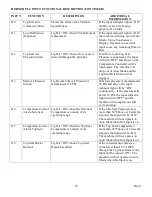
I10 

Top Seal and 
Volumetric Drive 

Shows the status of the Variable 
Speed Drives. 

If the input indicator light is “ON” 
the Drives are functioning 
properly, No Faults. 

I11 

Low Roll Sensor 
(Optional) 

Light is “ON” when Film Roll needs 
replacement. 

If the input indicator light is “ON” 
the machine will drop out of Auto 
Mode.  Using Touchscreen 
Display, Operator can override 
input to use any remaining film on 
Roll. 

I12 

Top Seal Air 
Pressure Switch 

Light is “ON” when a flow of air is 
detected through the plenums. 

If air flow to the Top Seal 
Plenums is not present, the Input 
will turn “OFF” and Power to the 
Temperature Controller will be 
interrupted.  The machine will 
drop out of Auto Mode and the 
Top Seal Belt Motor will be 
stopped. 

I13 

Main Air Pressure 
Switch 

Lights when the Air Pressure is 
maintained at 76 PSI. 

When air pressure is maintained at 
76 PSI and above, the input 
indicator light will be “ON” 
continuously.  If the pressure falls 
below 76 PSI, the input indicator 
light will turn “OFF” and the 
machine will complete one full 
cycle and stop. 

I14 

Temperature Control 
Alarm Side Seal 

Light is “ON” when the Side Seal 
Temperature is outside of it’s 
operating range. 

If the Side Seal Temperature is 
more than 50ºF above or below the 
setpoint, the Input will be “ON”.  
The machine will not operate in 
Auto Mode when this Input is on. 

I15 

Temperature Control 
Alarm Top Seal 

Light is “ON” when the Top Seal 
Temperature is outside of it’s 
operating range. 

If the Top Seal Temperature is 
more than 20ºF above or below the 
setpoint, the Input will be “On”.  
The machine will not operate in 
Auto Mode when this Input is on. 

I16 

Top Seal Heater 
Burnout 

Light is “ON” when a Top Seal 
Heater has failed. 

If the current sensor detects a 
value lower than 15.5 AMPS 
through the Top Seal Heaters, the 
Input will be turned “ON”.  The 
machine will not operate in Auto 
Mode when this Input is on. 


Summary of Contents for Hamer 540

Page 1: ...Rev 4 MODEL 540 OPERATION MANUAL 14650 28th Avenue North Plymouth MN 55447 4821 USA TELEPHONE 763 231 0100 800 927 4674 FAX 763 231 0101 WEBSITE www hamerinc com MADE IN THE USA...

Page 2: ......

Page 3: ...t the time ofpublication All product specifications are subject to change WARNING PERSONAL INJURY MAY RESULT FROM DISREGARDING THE FOLLOWING SAFETY PRECAUTIONS MACHINE IS TO BE PROPERLY CONNECTED TO Y...

Page 4: ......

Page 5: ...Speed Control Menu 8 Side Sealer Setup Menu 9 Side Sealer ON Delay Timer Menu 9 Side Sealer OFF Delay Timer Menu 10 Low Ice Delay Timer Menu 10 Lubricator Timer Menu Optional 11 Seal Wash Timer Menu...

Page 6: ...rake Cam 27 Film Clamp 28 Film Feed Chain Tension 28 Jaw Air Cylinder Adjustment Replacement 29 Jaw Liner Alignment 29 Jaw Liner Installation Instructions 30 Conveyor Adjustment 30 Prox Switch Activat...

Page 7: ...Rev 4 SECTION ONE MODEL 540 FORM FILL AND SEAL MACHINE...

Page 8: ......

Page 9: ...AVE ANY DOUBT ABOUT HAVING ENOUGH CONTRAST SEND SAMPLES TO HAMER LLC 4 TINTED FILM MUST HAVE CONSISTENT TINT LEVEL VARIATION CAUSES MISFIRE 5 THE FILM MUST BE ABLE TO UNWIND FROM THE ROLL WITH A FORCE...

Page 10: ...Rev 4 2 FILM ROLL BELT PATH STANDARD HIGH SPEED HIGH SPEED FILM ROLL BELT PATH STANDARD FILM ROLL BELT PATH...

Page 11: ...IRED 3 THE MACHINE SHOULD BE LOCATED WITH A MINIMUM OF 3 FT CLEARANCE ON ALL FOUR SIDES 4 ALL AIR INPUTS REQUIRE CLEAN DRY AIR 5 DO NOT DRILL HOLES IN THE TOP OR ANY SIDE OF CONTROL PANEL ALL WIRES MU...

Page 12: ...Rev 4 4 OPERATOR CONTROLS Electrical Control Panel Refer to the Electrical Parts List for Schematic when odering replacement parts for your control panel FIGURE ONE...

Page 13: ...lts and Knurled Wheels See Hot Air Sealer Set Up Shut Down procedures 7 Start Button one button on the Control Panel and one on the Remote with the Mode Selector Switch in the Auto mode depress the St...

Page 14: ......

Page 15: ...ubleshooting your machine When the main power is turned on to the machine Touchscreen Display activates OPERATOR INTERFACE This screen appears when the machine is powered up Press the BOTTOM RECTANGUL...

Page 16: ...MP SELECTOR MENU This menu allows the Machine Operator to select the number of times the Volumetric will dump before the bag will advance The average bags per minute rate that the machine is running i...

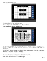
Page 17: ...uttons to adjust the speed The average bags per minute is displayed in the Bottom Rectangular Box Press the RETURN Button to go back to the Setup Menu TOP SEALER SPEED CONTROL MENU The belt speed of t...

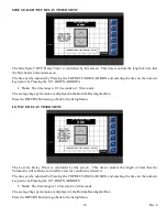
Page 18: ...Time Delay before the Side Sealer Solenoid turns on The timer starts timing when the bag stops advancing and the Fill Opening has opened The time can be adjusted by Pressing the TOP RECTANGULAR BOX a...

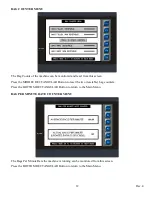
Page 19: ...displayed in the Bottom Rectangular Box Press the RETURN Button to go back to the Setup Menu LOW ICE DELAY TIMER MENU The Low Ice Delay Timer is controlled by this screen This timer controls the lengt...

Page 20: ...Button to go back to the Setup Menu SEAL WASH TIMER MENU OPTIONAL The Optional Seal Wash Timer is controlled by this screen This timer controls the length of time that the optional Seal Wash Solenoid...

Page 21: ...e MIDDLE RECTANGULAR Button to reset the two resetable bag counters Press the BOTTOM RECTANGULAR Button to return to the Main Menu BAG PER MINUTE RATE COUNTER MENU The Bags Per Minute Rate the machine...

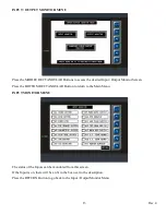
Page 22: ...tput Monitor Screen Press the BOTTOM RECTANGULAR Button to return to the Main Menu INPUT MONITOR MENU The status of the Inputs can be monitored from this screen If the Input is on there will be an X i...

Page 23: ...escription Press the RETURN Button to go back to the Input Output Monitor Menu COMBINED INPUT OUTPUT MONITOR MENU The status of the Inputs and Outputs can be monitored at the same time from this scree...

Page 24: ...OM RECTANGULAR Button to return to the Main Menu ALARM STATUS MONITOR MENU The status of any current alarms and the history of previous alarms can be viewed from this screen Press the SQUARE BOXES to...

Page 25: ...ride the low sensor and allow the machine to continue running until the roll is empty DOUBLE DUMP ALARM MENU If a Double Dump Condition is detected overfilled bag the machine will stop and drop out of...

Page 26: ...o Mode and the Volumetric Position Detector has been activated the film will then advance I6 Side Seal Limit Switch Light is ON when the Side Seal Bar is in the HOME position If this Input is not pres...

Page 27: ...ressure is maintained at 76 PSI When air pressure is maintained at 76 PSI and above the input indicator light will be ON continuously If the pressure falls below 76 PSI the input indicator light will...

Page 28: ...e air valve Q4 Low Product Detector Lights when product is at a low level in the Hopper The output indicator light is ON when the product level in the Hopper is below that of the Detector Q5 Lubricato...

Page 29: ...Film Clamp The film is clamped after the film stops moving Q14 Film Unwind Output turns ON the Air Valve for the Unwind Assist Pulls on Dancer after the film is clamped This re fills the Dancer in pr...

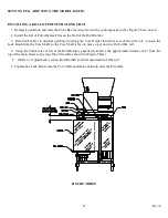
Page 30: ...ing the Core Holder into fiber core of the film roll Loosen the Lock Knob from the Core Shaft so the Core Shaft is free to move up or down with the film roll 4 Using the Crank raise or lower the Roll...

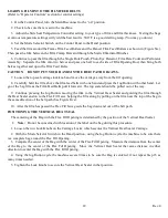
Page 31: ...he bag film as the Film Feed Belts pull it forward The top sealer should be pulled out of the way 9 Continue pressing the Jog Button moving the film to the Vertical Heat Sealer and guiding the film th...

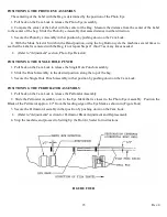
Page 32: ...eded Refer to Adjustment section Photo Eye Detector POSITIONING THE SINGLE HOLE PUNCH 1 Pull back on the Cam Lock to release the Single Hole Punch Assembly 2 Slide the Punch Assembly to the desired po...

Page 33: ...the Vertical Heat Sealer must move that same distance to maintain the bag width 2 The Photo Eye Bracket is designed to rotate from one side of the Film to the other side because the beam of the Photo...

Page 34: ...the edges of the Teflon Cloth Then remove the Pan Head Screws that hold the Teflon Cloth to the Seal Pad Rollers 4 Secure a new sheet of Teflon Cloth to the Seal Pad Rollers by using the same Pan Head...

Page 35: ...Tail Pulley Plate Next guide the belt through all the Idler Pulleys along the full length of belt path Then pull the belt around the Drive Pulley in the same manner as described in step 3 Repeat for...

Page 36: ...Valve This is achieved by the positioning of the Brake Cam With the Dancer Arm Film Feed Rollers set at the proper distance of 14 from the Frame Film Feed Rollers as shown in Figure Six with the machi...

Page 37: ...learance for the film to pass through the Film Clamp If the film hangs up on the Film Clamp then slightly adjust the Clamp Pivot again to achieve the clearance needed for free travel of the film CAUTI...

Page 38: ...le Cylinder Mount 5 Slide New Air Cylinder into place and fasten to Guide Rail Angle Cylinder Mount with Air Cylinder Jam Nut Note Keep Air Fitting Hole to top of Air Cylinder 6 Re install Clevis Jam...

Page 39: ...cure the two Conveyor Clamps one on each of the conveyor assembly located on the underside of the two Conveyor Supports Slide the Conveyors to the position mentioned above and secure in place PROX SWI...

Page 40: ...Rev 4 31 FIGURE EIGHT FIGURE NINE...

Page 41: ...r and noisy operation of these systems will result when replacement is necessary Inspect these parts for evidence of wear and replace as needed CAUTION DISCONNECT POWER BEFORE PERFORMING ANY INSPECTIO...

Page 42: ...d Belts will feed directly into the Hot Air Sealer s Feed Belts without slowing the flow of the machine Refer to Adjustment section Film Feed System 5 Run sample bags to determine the proper Temperatu...

Page 43: ...t Air Sealer s Film Feed Carriage so that the pinch point of the Film Feed Belts are approximately 1 2 from the leading edge of the product filled bag and also at the same time that same leading edge...

Page 44: ...ng Belt Tensioners KNURLING BELTS There are two Knurling Belts that press the hot film halves together to create a solid seal There may be a need to adjust the pressure of the Knurling Belts depending...

Page 45: ...til it reaches the set temperature and will fluctuate 10 degrees around the set temperature See Figure Two The recommended starting temperature is 250 F Increase the temperature until the seal is stro...

Page 46: ...and Bearings for wear or tear and replace if necessary 3 If the Belts are getting worn for best results change the full set WEEKLY These tasks should be done on a weekly schedule 1 Clean machine thor...

Page 47: ......

Page 48: ...tart to jog then stall out the Film Feed Motor on the Clutch No film between the belts and the fill opening Spray the belts and fill opening with water Pulse the Jog Button until the film is fed aroun...

Page 49: ...id not see it Locate the reason that the Photo Eye did not see the Eye Mark Does the film have an Eye Mark printed on it Is the film threaded between the Photo Eye and the Reflector Is the Eye Mark pa...

Page 50: ...roper operation especially the Film Clamp for proper clearance The brake of the Film Feed Clutch is not engaged properly Check that the Seal Pad Guards are set flush with the Teflon Cloth and the Seal...

Page 51: ...hot air plenums Inadequate pressure between the belts Speed is mismatched between the top V belts and the bag conveyor belts Increase the set point on the temperature control 20 at a time until the b...

Page 52: ...rtical and Horizontal alignment between the seal bar and seal pad teflon Adjust as necessary Adjust the film clamp to hold securely Rebuild or replace the fill opening cylinders if operating slow or a...

Page 53: ...damage and wear Check the pressure between the V pulleys particularly the two just before the fill opening They should apply equal pressure Adjust and or replace the orange runner clamp tubes Check t...

Page 54: ...DERING When ordering replacement parts give the part name part number model number of the machine and the serial number of the machine This will help greatly in supplying the correct parts in the leas...

Page 55: ...Rev 4 45 SECTION TWO MODEL 540 ASSEMBLY DRAWINGS...

Page 56: ......

Page 57: ...30 1 14135 PNEUMATIC ASSEMBLY 540 29 1 14134 DRIVE ASSEMBLY BELT PATH 28 1 14133 540 HOT AIR SEALER MAIN ASSEMBLY 27 1 14132 VOLUMETRIC ASSEMBLY 26 1 14131 VALVE ASSEMBLY 540 JAW CLUTHES 25 1 14130 J...

Page 58: ...S 8 8 2586 WASHER LOCK 3 8 SS 7 1 2585 WASHER LOCK 5 16 SS 6 2 2584 WASHER LOCK 1 4 SS 5 8 2579 WASHER 3 8 FLAT S S 4 1 2578 WASHER 5 16 3 2 2577 WASHER 1 4 2 8 2555 HHCS 3 8 16x1 SS 1 1 2531 NUT 5 16...

Page 59: ...T FINISH MATERIAL FRACTIONS 1 32 DECIMALS 2 PL 02 DECIMALS 3 PL 005 ANGLES 1 2 SHEET 1 OF 1 12 19 2007 SEE ECO 1643 1 9 26 06 NEW RELEASE SEE ECO 1320 DATE DESCRIPTION REV REVISIONS ITEM QTY PART NUMB...

Page 60: ...1 20 2006 2 SEE ECO 1643 12 19 2007 9 26 06 REVISIONS REV DESCRIPTION DATE 0 NEW RELEASE SEE ECO 1320 ITEM QTY PART NUMBER DESCRIPTION 15 1 13450 1 BRIDGE CLAMP ANGLE 14 1 9949 1 SEAL PAD WELDMENT VER...

Page 61: ...25 CONDUIT 3 8 7 2 3209 RING TERMINAL T COUPLE WIRE 6 REF 2869 HSHCS 6 32 X 1 5 1 2674 HSHCS 1 4 20 X 625 4 1 2584 WASHER LOCK 1 4 SS 3 22 2343 WIRE 14 GA BLACK STRANDED 2 5 2340 WRAP SPIRAL 1 2 DIAME...

Page 62: ...PHLP PAN HEAD 1 4 20 X 38 4 2 2532 NUT 3 8 16 3 1 2525 NUT NYLOCK 3 8 16 2 4 0635 FITTING ELBOW 1 8NPT 1 4 LINE 1 2 0634 1 8 PIPE x1 4 PLASTIC STRAIGHT CONN REVISIONS REV DESCRIPTION DATE New release...

Page 63: ...1 1 0645E NUT ELEC LOCK DWG NO 14314 2 00 DWH SURFACE FINISH TO BE 125 MICROINCHES REMOVE ALL BURRS BREAK ALL SHARP CORNERS UNLESS OTHERWISE SPECIFIED UNLESS OTHERWISE SPECIFIED DIMENSIONS ARE IN INC...

Page 64: ...CROINCHES B CONDUIT BOX ASSEMBLY FINISH TITLE 1 2 DRAWN BY FRACTIONS 1 32 DECIMALS 2 PL 02 DECIMALS 3 PL 005 ANGLES 1 2 SHEET 1 OF 1 14314 3 WASHER LOCK 1 4 SS 2 2 2542 HHCS 1 4 20x1 2 SS 1 2 2314 STR...

Page 65: ...2 ID x 16 63 18 4 13447 FILM HOLDING BAR 17 1 11234 2 CAM VALVE 16 1 11234 1 CAM VALVE 15 16 11228 Spring Retainer Rev 2 14 8 11223B BUSHING MODIFIED 13 2 11219 1 GUIDE BAR VERTICAL SEALER 12 16 3850...

Page 66: ...42 HHCS 1 4 20 X 1 2 4 12 2529 NUT 1 4 3 1 0931 NIPPLE 1 8 NPT CLOSE 2 1 0634 1 8 PIPE x1 4 PLASTIC STRAIGHT CONN 1 1 0633 FLOW CONTROL DWG NO 14315 00 T Pehrson SURFACE FINISH TO BE 125 MICROINCHES R...

Page 67: ...N 1 1 0033 HANDLE CRANK ITEM NO QTY PART NUMBER DESCRIPTION 92 1 22596 FLOW CONTROL 1 8 NPT 1 4 TUBE 91 1 14546 DANCER AIR CYLINDER ASSEMBLY 90 1 13855 BRACKET FILM CLAMP PIVOT 89 1 12811 THRUST BEARI...

Page 68: ...13 4 2948 NUT JAM 3 8 16 12 1 2830 COTTER PIN 11 2 2804 HHCS 1 4 20x7 8 SS 10 4 2718 HHCS 1 4 20x 62 SS 9 2 2585 WASHER LOCK 5 16 SS 8 8 2584 WASHER LOCK 1 4 SS 7 1 2578 WASHER 5 16 6 2 2550 HHCS 5 16...

Page 69: ...3222 1 BRACKET BRAKE VALVE 17 3 2908 HHCS 5 16 18x1 5 SS 16 2 2869 HSHCS 6 32 X 1 15 2 2865 SFHCS 5 16 18 X 62 SS 14 4 2859 SHCS 10 24 x 75 SS 13 2 2845 SHCS 5 16 18 x 1 2 SS 12 2 2763 HHCS 5 16 18x2...

Page 70: ...N SPRING 3 16 x 1 1 4 14 4 2586 WASHER LOCK 3 8 SS 13 4 2585 WASHER LOCK 5 16 SS 12 4 2584 WASHER LOCK 1 4 SS 11 4 2577 WASHER 1 4 10 2 2559 HHCS 3 8 16x2 00 SS 9 4 2558 HHCS 3 8 16x1 75 SS 8 4 2557 H...

Page 71: ...5 16 SS 5 4 2583 WASHER LOCK 10 SS 4 1 2578 WASHER 5 16 3 1 2547 HHCS 5 16 18x 62 SS 2 2 2515 1 SET SCREW SH 1 4 20 x 1 4 1 1 2137 1 LOCK KNOB ASSEMBLY ITEM FOR SHT 5 QTY PART NUMBER DESCRIPTION DWG N...

Page 72: ...0908 REGULATOR 1 8 NPT 2 1 0635 FITTING ELBOW 1 8NPT 1 4 LINE 1 1 0633 FLOW CONTROL 1 USE TEFLON TAPE ON ALL FITTINGS 1 3 AIR IN 10 1 9 1 8 1 7 1 6 1 5 1 1 1 5 1 4 1 2 1 NOTES AIR FLOW NOTES UNLESS OT...

Page 73: ...9 LIFT CRANK EXTENSION 31 1 10298 2 GEARBOX STOP BLOCK 30 1 10107 SPACER CONVEYOR STOP 29 1 9874 1 SPEED REDUCER 28 2 3273 Link 50 STAINLESS STEEL 27 2 3259 MASTER LINK 40 STAINLESS STEEL 26 4 3254B I...

Page 74: ...4 60 1 7 2 5 4 12 2 48 1 59 1 37 2 45 1 20 5 61 1 23 2 35 2 18 4 36 2 DWG NO 11161 6 D HENGEL SURFACE FINISH TO BE 125 MICROINCHES REMOVE ALL BURRS BREAK ALL SHARP CORNERS UNLESS OTHERWISE SPECIFIED...

Page 75: ...32 X 1 0 32 2 2971 KEY SQUARE 3 16 x 2 1 4 31 24 2965 CARRIAGE BOLT 5 16 x 3 4 30 8 2843 HHCS 5 16 18x2 SS FT 29 4 2804 HHCS 1 4 20x7 8 SS 28 9 2718 HHCS 1 4 20x 62 SS 27 2 2624 Key 3 16 X 1 Woodruff...

Page 76: ...E 1 33 6 22 6 10 32 24 40 46 4 24 40 10 32 31 24 12 16 61 4 59 2 60 8 26 8 58 4 25 36 15 16 DWG NO 11169 6 RSL SURFACE FINISH TO BE 125 MICROINCHES REMOVE ALL BURRS BREAK ALL SHARP CORNERS UNLESS OTHE...

Page 77: ...E 3 SEE NOTE 2 SEE NOTE 2 41 2 29 2 52 2 39 2 33 2 38 1 GREASE GREASE 31 2 ELECTRICAL REFERENCE 3 8 SEALTITE FLEXIBLE GRAY CONDUIT SEE SHEET 4 FOR BILL OF MATERIALS DWG NO 11169 6 RSL SURFACE FINISH T...

Page 78: ...20x7 8 SS 25 2 2624 Key 3 16 X 1 Woodruff Plain 24 36 2586 WASHER LOCK 3 8 SS 23 30 2585 WASHER LOCK 5 16 SS 22 12 2584 WASHER LOCK 1 4 SS 21 1 2583 WASHER LOCK 10 SS 20 16 2579 WASHER 3 8 FLAT S S 19...

Page 79: ...VE ALL BURRS BREAK ALL SHARP CORNERS UNLESS OTHERWISE SPECIFIED UNLESS OTHERWISE SPECIFIED DIMENSIONS ARE IN INCHES AND TOLERANCES ARE FRACTIONS 1 32 DECIMALS 2 PL 02 DECIMALS 3 PL 005 ANGLES 1 2 DATE...

Page 80: ...PROCKET 40JA15 1 1 40318 BUSHING 3 4 JA FINISHED ITEM QTY PART NUMBER DESCRIPTION DWG NO 40354 SHEET 1 OF 1 8 28 2013 REV DWG NO SIZE SCALE TITLE 40JA15 SPROCKET ASSEMBLY Hamer LLC MINNEAPOLIS MINNESO...

Page 81: ...PROCKET 40JA16 1 1 40318 BUSHING 3 4 JA FINISHED ITEM QTY PART NUMBER DESCRIPTION DWG NO 40355 SHEET 1 OF 1 8 14 2013 REV DWG NO SIZE SCALE TITLE 40JA16 SPROCKET ASSEMBLY Hamer LLC MINNEAPOLIS MINNESO...

Page 82: ...E TEFLON TAPE ON ALL AIR FITTING THREADS IF THE MACHINE HAS A HANDLE OPTION THEN ITEM PLUG IS REPLACED WITH 0677 1 3 REVISION ECO 0928 0677 WAS 3261 2 2 MOUNT ASSEMBLY TO FRAME USING 2709 2 AND 2583 2...

Page 83: ...IMENSIONS APPLY AFTER FINAL SURFACE TREATMENT 3 STAMP PART WITH NUMBER IN POSITION SHOWN 5 31 2007 NEW RELEASE SEE ECO 1474 0 DATE DESCRIPTION REV REVISIONS ITEM Default QTY PART NUMBER DESCRIPTION 9...

Page 84: ...1 PLATE TAIL PULLEY 2 4009 SPRING COMPRESSION ref 4007 ICE HOPPER 6 2 4005 SUPPORT SPRING 1 4003 ANGLE 2 4002 BACKUP SLIDE 2 4001 SLIDE PLASTIC 1 3557 NUT JAM 1 5 12 18 3269 1 PULLEY IDLER 2 3214 1 P...

Page 85: ...QTY PART NUMBER DESCRIPTION 18 1 13851 535 FLEX FILL FRAME 17 4 12332 O Ring 16 4 11491 NUT PLATE 15 1 11490 BEARING PLATE 14 4 10343 PULLEY ASSEMBLY A IDLER 13 ref 4007 ICE HOPPER 6 12 4 3213 3 HUB...

Page 86: ...QUICK EXHAUST 1 4 NPT 26 1 3557 NUT JAM 1 5 12 25 1 2990 WASHER FLAT 1 1 2 24 2 2915 HHCS 1 2 13x2 1 2 SS FT 23 6 2904 NUT JAM 1 2 13 22 4 2903 HHCS 1 2 13 X 2 21 2 2843 HHCS 5 16 18x2 SS FT 20 2 276...

Page 87: ...S DATE DRAWN BY MINNEAPOLIS MINNESOTA Hamer LLC TITLE SCALE SIZE REV 09 T PEHRSON 1 4 13830 BELT PATH JAW ASSEMBLY 4 6 05 SHEET 4 OF 9 ITEM PARTS IN BILL QTY PART NUMBER DESCRIPTION 5 2 13840 6 JAW LI...

Page 88: ...KET PULLEY 20 2 4013 1 HUB 19 1 4011 1 PLATE TAIL PULLEY 18 2 4009 SPRING COMPRESSION 17 2 4005 SUPPORT SPRING 16 1 4003 ANGLE 15 2 4002 BACKUP SLIDE 14 2 4001 SLIDE PLASTIC 13 2 3269 1 PULLEY IDLER 1...

Page 89: ...SOTA Hamer LLC TITLE SCALE SIZE REV 09 T PEHRSON 1 6 13830 BELT PATH JAW ASSEMBLY 4 6 05 SHEET 6 OF 9 13830 DWG NO 2 10 9 2 3 6 2 3 6 5 3 SEPERATOR 8 1 4 2 ITEM shown part QTY PART NUMBER DESCRIPTION...

Page 90: ...SCALE SIZE REV 09 T PEHRSON 1 6 13830 BELT PATH JAW ASSEMBLY 4 6 05 SHEET 7 OF 9 ITEM RAIL PARTS QTY PART NUMBER DESCRIPTION 9 2 13844 1 RAIL PULLEY 8 16 10342 1 HUB 7 16 3269 1 PULLEY IDLER 6 16 2908...

Page 91: ...WARD BOX 4 IF NO TOP TRIM WITH TOP TRIM 4 1 13 1 8 1 7 1 18 1 12 2 2 2 3 3 19 1 1 6 15 2 14 1 10 3 3 3 11 1 2 REVISIONS REV DESCRIPTION DATE NEW RELEASE ECO 1101 11 01 05 1 Revision See ECO 2371 05 10...

Page 92: ...TE FLAP 33 1 11038 CHUTE FLAP 32 1 11037 CHUTE 31 1 10002 DRIP PAN 30 1 9987 ICE DETECTOR PROX SWITCH ASSY 29 1 9986 1 WIGGLER ASSEMBLY 28 1 9985 ICE SLAPPER ASSEMBLY 27 1 9890 VOLUMETRIC FILLER 26 3...

Page 93: ...ER 11 1 3282 COVER ICE SLAPPER 10 1 3281 ICE SLAPPER BUMPER 9 3 2699 SFHCS 1 4 20 UNC X 3 4 LG 8 4 2654 HSHCS 1 4 20 X 1 7 5 2614 SFHCS 1 4 20 X 1 2 6 8 2584 WASHER LOCK 1 4 5 5 2577 WASHER 1 4 4 2 25...

Page 94: ...PLASTIC 1 8 4 1 10 3 11 5 9 7 MOUNT BRACKET ON THE OUTSIDE OF HOPPER IF REQUIRED USE THE BRACKET AS A TEMPLATE TO DRILL HOLES 2 6 REVISIONS REV DESCRIPTION DATE 0 NEW RELEASE SEE ECO 2470 8 18 2010 1...

Page 95: ...OF 1 9987 DWG NO 3 SHOWN FOR REFERENCE ONLY SHOWN FOR REFERENCE ONLY 10 2 4 5 9 DETECTOR LOW LEVEL 3353 1 11 2 6 2 2 1 1 3 8 VOLUMETRIC ASSEMBLY 1 7 2 REVISIONS REV DESCRIPTION DATE 0 NEW RELEASE SEE...

Page 96: ...SIONS ARE IN INCHES BREAK ALL SHARP CORNERS UNLESS OTHERWISE SPECIFIED UNLESS OTHERWISE SPECIFIED AND TOLERANCES ARE FRACTIONS 1 32 DECIMALS 2 PL 02 DECIMALS 3 PL 005 ANGLES 1 2 SHEET 1 OF 1 1 6 5 2 4...

Page 97: ...PTION 25 1 34225 MOTOR 3 4 HP 3 PH 60Hz 24 1 3272 CHAIN 50 23 2 10518 DRUM PULLEY 22 2 10103 PLATE NUT 21 1 10040 GEAR BOX MOUNTING PLATE 20 1 3360 SEAL RING 19 8 3337 1 WIRE 14 GUAGE GREEN 18 1 3327...

Page 98: ...G NO 14132B DWG NO Hamer LLC TITLE SURFACE FINISH TO BE 125 MICROINCHES REMOVE ALL BURRS BREAK ALL SHARP CORNERS UNLESS OTHERWISE SPECIFIED UNLESS OTHERWISE SPECIFIED DIMENSIONS ARE IN INCHES AND TOLE...

Page 99: ...ARE MINNEAPOLIS MINNESOTA DIMENSIONS ARE IN INCHES UNLESS OTHERWISE SPECIFIED B SIZE SCALE 14133 TITLE FINAL TOP ASSEMBLY 1 8 Hamer LLC DRAWN BY DATE FRACTIONS 1 32 DECIMALS 2 PL 02 DECIMALS 3 PL 005...

Page 100: ...bly Floating Block 26 2 13251 PLATE GEAR RETAINER 25 2 12355 Bar Plate Strengthening 24 2 12353 Block Base Hanger 23 4 12162 BLOCK HANGER 22 1 10858 CYLINDER 21 4 10755 Carriage Rod HAS 20 2 9613 REDU...

Page 101: ...ATE 1 SEE ECO 0956 5 26 2005 2 REVISION SEE ECO 1077 same front belt 9 27 2005 3 ECO 2517 changed drawing to match progression 10 22 2010 ITEM 13460 6 QTY PART NUMBER DESCRIPTION 30 REF 13528 TRIMMER...

Page 102: ...5 1 2944 HOLE PLUG 4 2 2598 SHCS 1 4 20 X 3 4 SS 3 4 2316 STRAIN RELIEF LARGE 2 5 2314A NUT ELEC LOCK 1 1 2314 STRAIN RELIEF SMALL 2 2 2 3 3 NOTE 2x 13981 NOT SHOWN 12391 12391 JUNCTION BOX ASSEMBLY 1...

Page 103: ...ER HEATER 13 1 11795 PLUG 1 8npt 12 1 11714 THERMOCOUPLE 11 8 2698 HHCS 1 4 20 X 1 25 10 8 2655 HSHCS 6 32 X 1 2 9 8 2585 WASHER LOCK 5 16 8 16 2584 WASHER LOCK 1 4 7 8 2577 WASHER 1 4 6 16 2543 HHCS...

Page 104: ...Plate Strengthening 24 1 12219 BLOCK SCRAP BLOWOFF 23 2 12165 Drive Pulley Assembly 22 1 12050 2 REDUCER 21 2 11705 Knurling Shaft 20 1 10433 TENSIONER 19 1 3360 SEAL RING 18 1 3326 FITTING 3 8 CONDUI...

Page 105: ...IL HANGER 32 4 13462 HAS BOGEY ASSEMBLY 31 1 13459 SUSPENDED PULLEY RAIL 30 REF 13458 MAIN PLATE NON MOTOR SIDE HOT AIR SEALER 29 REF 13457 MAIN PLATE MOTOR SIDE HOT AIR SEALER 28 2 12386 Pulley Assem...

Page 106: ...3VX 3 1 3287B BUSHING ICE SLAPPER 2 1 3251 SHOULDER SCREW 1 2 DIA X 1 LG 1 2 3176B Bushing 625 OD X 5 ID X 1 00 LG DWG NO 13462 01 SURFACE FINISH TO BE 125 MICROINCHES REMOVE ALL BURRS BREAK ALL SHAR...

Page 107: ...leys and hardware from BOM that aren t needed if ECO 2517 removed extra pulley and hardware excluded 3 3 9 28 2005 Revision see eco 1077 first build corrections 2 DATE DESCRIPTION REV REVISIONS ITEM 1...

Page 108: ...ACER 17 2 3254 SPROCKET 40 IDLER 16 2 3253 SPROCKET FILM FEED DRIVE 15 2 3212 3 DRIVE SHAFT 14 1 3211 1 TENSIONER 13 5 2831 KEY SQUARE 3 16 x 3 4 12 1 2705SS HHCS 1 2 13x1 SS 11 1 2587 WASHER LOCK 1 2...

Page 109: ...SHING 3 4 JA FINISHED 1 1 40317 SPROCKET 40JA18 ITEM QTY PART NUMBER DESCRIPTION DWG NO 40319 SHEET 1 OF 1 8 14 2013 REV DWG NO SIZE SCALE TITLE 40JA18 SPROCKET ASSEMBLY Hamer LLC MINNEAPOLIS MINNESOT...

Page 110: ...E ASSEMBLY 540 SEALER OPENING 7 1 14135A VALVE REGULATOR ASSY 540 H A S 6 1 11797 H A S PRESSURE SENSOR 5 1 10550 CONDUIT FITTING 1 2 STRAIGHT 4 1 4166 PRESSURE SWITCH 3 5 3326 FITTING 3 8 CONDUIT 2 9...

Page 111: ...4 NPT 3 8 LINE 2 2 0654 1 NIPPLE 1 4 CLOSE 1 3 0645E NUT ELEC LOCK DWG NO 14135A 00 T PEHRSON 1 4 14135A A VALVE REGULATOR ASSY 540 H A S 11 4 05 SHEET 1 OF 1 SURFACE FINISH TO BE 125 MICROINCHES REM...

Page 112: ...LEC LOCK 1 1 0635 FITTING ELBOW 1 8NPT 1 4 LINE DWG NO 14135B 00 T PEHRSON SEE BILL OF MATERIAL 1 3 14135B A VALVE ASSEMBLY 540 SEALER OPENING 11 04 05 SHEET 1 OF 1 SURFACE FINISH TO BE 125 MICROINCHE...

Page 113: ...8 3 11257 3 8 NPT CLOSE NIPPLE GALV 7 1 4167 FITTING 1 4NPT 5 32 LINE STRAIGHT 6 4 2584 WASHER LOCK 1 4 SS 5 2 2577 WASHER 1 4 4 2 2543 HHCS 1 4 20x 75 SS 3 2 2542 HHCS 1 4 20x1 2 SS 2 1 0970 FITTING...

Page 114: ...LINE 1 1 0968 FITTING 3 8 NPT 1 4 NPT DWG NO 14135D 00 T PEHRSON 1 1 5 14135D B MANIFOLD ASSEMBLY 540 MAIN 11 04 05 SHEET 1 OF 1 SURFACE FINISH TO BE 125 MICROINCHES REMOVE ALL BURRS BREAK ALL SHARP C...

Page 115: ...LY 4 1 11012 RAIL SLIDE PERF 3 1 11011 SHAFT SLIDE ROD PERF 2 1 2735 SquHd Set Screw 1 4 20 x 3 4 1 3 2609 SHCS 10 24 X 875 SS ITEM QTY PART NUMBER DESCRIPTION DWG NO 14136 4 T PEHRSON SURFACE FINISH...

Page 116: ...PART NUMBER DESCRIPTION DWG NO 40434 SHEET 1 OF 1 10 24 2013 REV DWG NO SIZE SCALE TITLE PHOTO EYE ASSEMBLY Hamer LLC MINNEAPOLIS MINNESOTA A 40434 1 3 DRAWN BY MATERIAL FINISH HEAT TREAT DATE FRACTIO...

Page 117: ...SS ITEM QTY PART NUMBER DESCRIPTION DWG NO 40433 SHEET 1 OF 1 10 24 13 REV DWG NO SIZE SCALE TITLE PHOTO EYE SUPPORT ASSEMBLY Hamer LLC MINNEAPOLIS MINNESOTA A 40433 1 3 DRAWN BY MATERIAL FINISH HEAT...

Page 118: ...P LOCKING 2 4 2595 SHCS 10 24x 5 SS 1 4 2583 WASHER LOCK 10 SS ITEM QTY PART NUMBER DESCRIPTION DWG NO 40285 SHEET 1 OF 1 6 26 07 REV DWG NO SIZE SCALE TITLE PHOTO EYE MOUNT ASSY 540 Hamer LLC MINNEAP...

Page 119: ...35 FITTING ELBOW 1 8NPT 1 4 LINE 1 1 0634 1 8 PIPE x1 4 PLASTIC STRAIGHT CONN ITEM QTY PART NUMBER DESCRIPTION REVISIONS REV DESCRIPTION REVISED BY DATE 0 NEW RELEASE ECR 4271 11 26 2013 DWG NO 40470...

Page 120: ...NG 2 4 2595 SHCS 10 24x 5 SS 1 4 2583 WASHER LOCK 10 SS ITEM QTY PART NUMBER DESCRIPTION DWG NO 40284 1 PETE SURFACE FINISH TO BE 125 MICROINCHES REMOVE ALL BURRS BREAK ALL SHARP CORNERS UNLESS OTHERW...

Page 121: ...x7 8 SS 10 2 2786 NUT JAM 1 4 20 9 2 2718 HHCS 1 4 20x 62 SS 8 2 2614 SFHCS 1 4 20 X 1 2 SS 7 5 2585 WASHER LOCK 5 16 SS 6 2 2584 WASHER LOCK 1 4 SS 5 2 2577 WASHER 1 4 4 2 2549 HHCS 5 16 18 X 7 8 SS...

Page 122: ...HCS 5 16 18 X 7 8 4 4 2544 HHCS 1 4 20 x 1 3 1 2532 NUT 3 8 16 2 2 2531 NUT 5 16 18 1 4 2529 NUT 1 4 DWG NO 14137 00 T PEHRSON SURFACE FINISH TO BE 125 MICROINCHES REMOVE ALL BURRS BREAK ALL SHARP COR...

Page 123: ...M QTY PART NUMBER DESCRIPTION 19 1 11365 COVER HAS 18 4 11310 GAS SPRING ASSEMBLY 17 1 11177 1 GUARD HAS LEFT 16 1 11176 2 GUARD HAS RIGHT 15 1 11173 1 COVER BELT PATH 14 4 3455 BRACKET SHOCK 13 8 345...

Page 124: ...CALE TITLE 1 2 Hamer LLC DRAWN BY DATE HEAT TREAT FINISH MATERIAL FRACTIONS 1 32 DECIMALS 2 PL 02 DECIMALS 3 PL 005 ANGLES 1 2 NO TRIMMER OPTION 540 HAS 1 REMOVE ALL BURRS AND SHARP EDGES 2 ALL DIMENS...

Page 125: ...onents Unapproved services modifications and service parts All obligations of Hamer LLC under this warranty are terminated if the machinery is modified or altered in any way not expressly approved by...

Page 126: ...TY GROUND READ INSTRUCTION MANUAL THOROUGHLY BEFORE OPERATING THIS MACHINE DISCONNECT ELECTRICAL AND AIR POWER BEFORE PERFORMING MAINTENANCE OR REPAIR WORK DO NOT OPERATE MACHINE WITH SAFETY GUARDS RE...

Reviews: