background image


P a g e

 | 

30


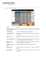
FILM TENSIONS PAGE 

Password Level 1 


Controls 
 

Functions

Start Wrap Film Tension 

Used to set the film tension to be applied at the beginning of the cycle. 
 

Top/Bottom Wrap Film Tension 

Used to set the tension of the film to be applied to the top and bottom of 
the load (separate values). The ratio is measured after the pre-stretch. 
Independent from pre-stretch ratio. 
 

Wrap Upward/Downward 

Used to set the tension of the film to be applied to the load while wrapping 
upward or downward. The tension is measured after the pre-stretch. 
Independent from pre-stretch ratio. 
 

Save / Save As 

Press  the  Save  button  to  save  new  settings  to  an  existing  wrap  pattern. 
Press  the  Save  As  button  to  save  a  new  wrap  pattern  under  a  specific 
name. 
 

Login 

The operator must login the page in order for the Save button to appear. 


Note

: Changes made to values on the current values pages will be applied to the load currently present in the 

wrapping zone only. Press the Save button if you want the changes to be applied to all future loads. 


Summary of Contents for Wulftec WCA-SMART

Page 1: ...P a g e 1 SO 160831 1 Emhart Teknologies Stanley User Reference Guide to Wulftec Equipment WCA SMART...

Page 2: ......

Page 3: ...cal publication of Wulftec International Inc 2013 Wulftec International Inc All rights reserved Published by Wulftec International Inc 209 Wulftec Ayer s Cliff Quebec Canada J0B 1C0 Author Wulftec Int...

Page 4: ...Standard 56 Mode of Operation In Line Top Sheet 57 Film Loading 58 In Line Top Sheet Film Loading 60 Clamp Loading Procedure 61 Pre stretch Ratios Chain Driven 62 Pre stretch Ratios Belt Driven 63 Pr...

Page 5: ...treal We take pride in knowing that our commitment to excellence just can t be beat Wulftec is a member of the DURAVANT family of companies Duravant is a global engineered equipment company with manuf...

Page 6: ...o have been subjected to misuse neglect or that has been repaired or altered by unauthorized personnel Defective parts must be returned to Wulftec within thirty 30 days of shipment of a replacement an...

Page 7: ...formation on unpacking transport storage use safety maintenance repairs and diagnostics intended to help machine users maintain the machine in proper and safe working order The manual must be kept in...

Page 8: ...is inappropriately used by untrained personnel or if it is used for purposes it is not intended for In order to avoid operating errors and to assure quick rectification of faults the operating instruc...

Page 9: ...mages In case of goods in containers make sure that container as well as locks or seals are checked by responsible persons of the shipping company or the carrier If containers are damaged or locks and...

Page 10: ...presentative For the customer it is recommended to obtain a written confirmation from the personnel that the contents of these operating instructions have been read Knowledge about the contents of the...

Page 11: ...s customer service department 9 The machine must be cleaned using a dry cloth or light detergents only The use of solvents or other type of strong cleaners is to be avoided 10 Only authorized personn...

Page 12: ...sure that no unauthorized persons work on the machine In order to avoid personal injury the working clothes of the operating and maintenance personnel must comply with the regulations for the preventi...

Page 13: ...ase check equipment and note all safety labels Make sure the personnel are vigilant and obey these warnings Shown below are typical labels that could be placed on the equipment PLACED ON ALL CONTROL P...

Page 14: ...placed in a clean and dry place If the machine is unpacked protect it from dust and avoid placing objects on it INTENDED USE The safe operation of the machine can only be assured when using the machi...

Page 15: ...ng 4 inches deep in concrete minimum o Mechanical anchors KB from Hilti 4in minimum engagement into concrete o Chemical anchors threaded rod Gr 2 Epcon system 3 minimum engagement into concrete Enclos...

Page 16: ...rntable 5 Install all the conveyor electrical conduits under the conveyor using the mounting clamps B 6 Connect and secure all electrical wires photoeyes motors lanyard e stop etc according to electri...

Page 17: ...cated in the bottom left side on the enclosure 15 Power up machine 16 Verify PLC inputs one by one using the electrical schematics to make sure wiring is done properly to avoid damages to the machine...

Page 18: ...er to drawing below Make sure the top sheet autoheight photoeye is aligned with the previous conveyor and the entrance photoeye is aligned on the top sheet conveyor 60 9 Conveyor junction Auto Height...

Page 19: ...top sheet legs Make sure the legs are open to fit the cradle in between When the cradle is in position push the legs inward Tighten the 3 bolts on each leg using a 2 key You can rest the cradle on th...

Page 20: ...curtains components using the top light beams as guide 6 The alignment mode is automatically activated when the light curtain is switched on if the light beams are not yet aligned or the light path is...

Page 21: ...question is situated at the entrance of the machine Outfeed Indicates that the component in question is situated at the exit of the machine Overlap Amount of film covering the preceding layer while w...

Page 22: ...P a g e 22 MAIN COMPONENTS WCA SMART Enclosure control panel Carriage film delivery system Turntable Ring gear support drive system Film Clamp Cut wire and wipe system Conveyor line...

Page 23: ...nstalled on the unistrut Tower Motor Brake Gearbox Group This group is responsible for making the carriage trolley go up and down Motion is assured by sprockets and chains situated on each side of the...

Page 24: ...ermine the problem RESET MODE Each time a manual screen is accessed you will be prompted to initialize the system before start mode is possible The reset mode is active only when the START STOP button...

Page 25: ...n an object entered the zone incorrectly or the light curtain beam was obstructed Follow instructions on the machine s touch screen Load Release Located at the end of a conveyor Press this button to r...

Page 26: ...the machine Maintenance to Do Displays the maintenance operations to carry out When maintenance is complete go to the Maintenance active page to acknowledge completion Follow the warning sign yellow...

Page 27: ...to the conveyor side rails S S Film Roll SSSS means the name of the film roll that has been predetermined into the roll film setting page With this switch you can choose two types of rolls Open Clamp...

Page 28: ...e autoheight photoeye position could affect the overwrap In inches If value is not accurate please refer to the Film roll settings page Top Wraps This selector determines the amount of stretch wrap ap...

Page 29: ...plastic feeding at the beginning of the load Feed after Load Used to select time of plastic feeding at the end of the load Feed after Cut Used to select time of plastic feeding after the cut Conveyor...

Page 30: ...e tension of the film to be applied to the load while wrapping upward or downward The tension is measured after the pre stretch Independent from pre stretch ratio Save Save As Press the Save button to...

Page 31: ...es the width of the film output from the carriage It allows the machine to re adjust the calculations used for overlap and overwrap upward Higher film tension Lower film width Distance Between PE And...

Page 32: ...pattern to be used with low loads Waiting Time on 1 st Outfeed Used to set the time during which the machine will pause to allow for load weighing Number of Top Wraps in Secure Top Sheet Rotation Spee...

Page 33: ...g To Be Wrapped This selector determines the speed for the wrapper to use when in Energy Saving Mode Applies to the rotation speed as well as the carriage up down speeds Forklift Load Picked Up Timer...

Page 34: ...t the end location until the next movement Cut from Left this button will allow the top sheet to be cut from the left to the right Cut from Right this button will allow the top sheet to be cut alterna...

Page 35: ...Use the multi function switch on the control panel to move the rotation Rotation Speed Used to set the speed of the rotation in rpm in manual mode All alarms will be active when operating at 2 rpm or...

Page 36: ...l movement Use the multi function switch on the control panel to rotate the top sheet roll Top Sheet Push Bar Used for the push bar movement Use the multi function switch on the control panel to open...

Page 37: ...rols Functions Set Date and Time Used to set the date and time displayed on the HMI Shift Schedule This page represents the start and end time of the plant s three shifts day evening and night Just en...

Page 38: ...Wulftec Press the desired button in order to restore the default settings Restore Buttons Customer Press the desired button in order to restore the settings that were last saved using the Save button...

Page 39: ...s Functions Add User Group Press to add users group Delete User Group Press to delete users group Modify Group Membership Press to define users group accesses Change User Properties Press to change th...

Page 40: ...s the machine spent in Run mode Machine Stopped by Alarm For each shift indicates the number of minutes that the machine was in stop mode because of an alarm and an active alarm Machine Stopped by Ope...

Page 41: ...ndicates the machine R P M from the last cycle completed Number of Turns in Last Cycle Indicates the number of turns wrap layers done during the last cycle completed Actual Rotation Position Displays...

Page 42: ...ontrols Functions Conveyor Time For Loads Per Hour Press this button to set the time needed for the load to go through the wrapping conveyor this time will be added to the wrap cycle time to calculate...

Page 43: ...pped since the machine was first started Hour Counter Counts the amount of hours of operation since the machine was first started Resettable Cycle Counter Counts the amount of wrapping cycles since th...

Page 44: ...ror occurred Alarm Banner Displays the alarm of the machine To acknowledge the alarm s press Acknowledge Alarm or Acknowledge All Alarms Silence Alarm Used to stop the alarm buzzer This does not stop...

Page 45: ...to be carried out The maintenance history lists the completed and acknowledged maintenances of the machine Alarm Banner Displays the alarm of the machine To acknowledge the alarm press ACK Alarm ACK...

Page 46: ...ed With Current Roll Displays the number of pallets that can be wrapped with the film left in the current roll Real Time Film Use Displays the film use in ounces in real time Average Film Ounces per P...

Page 47: ...btain the following information Cycle 30 Pattern Indicates the selected cycle and the wrap pattern that was used for this pallet Weight Indicates the weight in ounces of film used on the selected pall...

Page 48: ...iage top plate Second when the gate is unlocked half way the flag should not trigger the prox To obtain the results shown in steps 1 and 2 loosen the two 2 screws then slide the flag and tighten the s...

Page 49: ...pendicular to the electrical terminal block C 8 Rearm the emergency stop circuit Caution the pre stretch motor could restart For PowerFlex 523 make sure that parameter T095 is set to 10 9 Make sure th...

Page 50: ...and use the sensor Green The green LED indicates power When this indicator is lit power is on Amber Yellow The amber or yellow LED indicates status This indicator will light up when an output signal i...

Page 51: ...ensor features two LED indicators to help you program and use the sensor Green The green LED indicates power When this indicator is lit power is on Amber Yellow The amber or yellow LED indicates outpu...

Page 52: ...P a g e 52 PHOTOEYE ADJUSTMENT DARK LOAD LASER 1 Potentiometer Dark Load Photoeye Potentiometer This is used to adjust the photoeye sensitivity...

Page 53: ...against the top bolt to allow the carriage to reach the maximum wrap height of the machine the autoheight photoeye will stop the carriage at the top of the load in a normal cycle If your loads all ha...

Page 54: ...e load centered with the clamp as shown in the drawing below To adjust the reed switch A you will have to use a Philips screwdriver on the screw slide the bracket and reed switch and then secure it in...

Page 55: ...n the carriage gate c Spring loaded rollers adjusted too close to the pre stretch rollers could cause premature wear of the blue compound 3 If the middle roller is crooked you can play with the screws...

Page 56: ...pattern 5 Machine waits for a load 6 Load enters wrap zone and is centered automatically 7 If Wrapping mode is deactivated operation will move to step 22 8 If Wrapping mode is active the rotation begi...

Page 57: ...re feed delay set in HMI is expired the rollers will start feeding the plastic 5 The plastic is applied over the load If the top of the load is uneven the conveyor will stop and the top sheet structur...

Page 58: ...nd leave a film tail long enough to be able to close the door and reach the clamp jaws 11 Place the film tail in the clamp by wedging it in between the spring loaded clamp jaws It is possible to open...

Page 59: ...In a wrap cycle during which the rotation is active and the pre stretch motor stops working for more than three 3 seconds the machine will return to home position then go in stop state The cause is a...

Page 60: ...the casters and the first roller 3 Make sure the plastic goes down to at least the top sheet clamp and between the flappers 4 Use the feed plastic and cut plastic buttons to feed and cut the extra pl...

Page 61: ...61 CLAMP LOADING PROCEDURE 1 The clamp is closed 2 Open the clamp manually or pneumatically 3 Place the film between the clamp jaws 4 Close the clamp jaws manually or pneumatically to keep the film i...

Page 62: ...K00015 30 0MSPK00011 175 166 8 16 0MSPK00015 32 0MSPK00014 185 14 0MSPK00008 30 0MSPK00011 200 14 0MSPK00008 32 0MSPK00014 225 13 0MSPK00016 32 0MSPK00014 250 12 0MSPK00022 32 0MSPK00014 275 14 0MSPK0...

Page 63: ...85 15 T 0MSPK00124 32 T 0MSPK00129 187L050 0MCHN00046 200 14 T 0MSPK00130 32 T 0MSPK00129 187L050 0MCHN00046 225 13 T 0MSPK00132 32 T 0MSPK00129 187L050 0MCHN00046 250 12 T 0MSPK00168 32 T 0MSPK00129...

Page 64: ...00130 30 0MSPK00128 187L050 0MCHN00046 200 14 0MSPK00130 32 0MSPK00129 187L050 0MCHN00046 225 13 0MSPK00132 32 0MSPK00129 187L050 0MCHN00046 250 12 0MSPK00168 32 0MSPK00129 187L050 0MCHN00046 275 14 0...

Page 65: ...ng the set screws If necessary use a puller 6 Using the pre stretch chart in the manual select desired pre stretch and find appropriate pulley kit pulley belt chain for the selected pre stretch 7 Inst...

Page 66: ...nal identification tag to lock out the main switch to remove electricity from machine 2 Turn off the air using a padlock and lock out the air switch on the FR to remove air from machine 3 Verify that...

Page 67: ...off which indicates that the door is unlocked 4 Open the fence door 5 Carry out the lock out tag out LOTO procedure if applicable 6 Carry out the work to be done inside the safety fencing zone 7 Exit...

Page 68: ...rapping strapping equipment must be secured using chains or belts resting on an easel etc at all times during maintenance or repair works even when machine power is out in order to avoid unexpected or...

Page 69: ...ound the shaft seals and recheck the oil level adjust if necessary Subsequent oil changes should be made after 25 000 hours or as a part of a regular maintenance program this frequency is highly appli...

Page 70: ...P a g e 70 REDUCER CHART Legend F Refill Plug V Vent Plug L Level Plug D Drain Plug...

Page 71: ...s every six 6 months or as a part of your regular maintenance program If necessary apply grease to chains The chain tension should be checked on a regular basis The proper tension for the chain is app...

Page 72: ...rom under the top plate of the carriage and moving the motor using the slots provided The pre stretch chain tension may be adjusted by using the cam sprocket This cam has an eccentric hole and may be...

Page 73: ...ify for radial an axial movement of the inner race When movement is more than 1 32in replace all four bearings CARRIAGE TROLLEY Pre stretch roller bearings Chain tensioners 1 on each chain Wheels 4 in...

Page 74: ...n The lower section is for aligning the v groove carriage mounting plates Do not over tighten and assure that both chains are equal in tension Once set hold the adjustment nut and tighten the locknut...

Page 75: ...nister and it is strongly recommended to blow the assembly with compressed air every 2 800 hours of machine operation BEARING Lubrication of the bearing component is provided through the auto lube sys...

Page 76: ...side until you reach the maximum line CONVEYOR When required to stand on the conveyor for any reason power to the machine must be cut then put a proper thickness board large as the conveyor on the to...

Page 77: ...INTENANCE Operation Frequency Check chain or belt tension on pre stretch Check tension on carriage trolley chain Grease carriage rails Visually inspect ring gear teeth Remove build up and grease if ne...

Page 78: ...P a g e 78 MAINTENANCE LOG List of maintenance and or repair operations carried out on the machine Date Description of operation...

Page 79: ...rop is sufficient to fault the system Verify if sufficient air pressure is applied to the pneumatic system Verify for proper Filter Regulator operation Variable frequency drive VFD fault Each time tha...

Page 80: ...nsing range 1 16in Push arm out during rotation The cut and wipe arm is taken out of its retracted position during the rotation motion Make sure all bolts are tightened properly on wipe arm Proper air...

Page 81: ...too clear for the type of photoeye Obstacle detected during top sheet motion The top sheet is in motion the photoeyes detect obstacles in the top sheet path Remove possible obstacles from the top she...

Page 82: ...er you may find that the part is a part of a sub assembly If this is the case find the sub assembly drawing to obtain the correct number 3 You are ready to contact your local distributor OR 1 Since Wu...

Reviews: