NOTE: DIAGRAMS & ILLUSTRATIONS ARE NOT TO SCALE.
NOTE: DIAGRAMS & ILLUSTRATIONS ARE NOT TO SCALE.
11
UNIVERSAL
MALE
ADAPTER
EXISTING
B VENT
SECTION
EXISTING
B VENT
SECTION
UNIVERSAL
FEMALE
ADAPTER
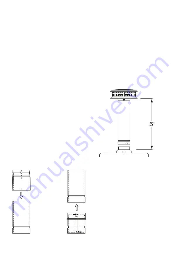
FIG. 10A
FIG. 10B
FIG. 10 - MALE AND FEMALE UNIVERSAL
ADAPTERS
Using the holes in the outer wall of the
adapter as a guide, drill two holes through
in the outer wall (only) of the gas vent. Be
careful not to penetrate the inner liner of the
gas vent. Secure the adapter to the gas vent
section with two 1/4” maximum length sheet
metal screws (provided).
The top (outlet) end of the system has now
been converted to the DuraVent Model BV
joint coupling design.
FEMALE ADAPTER - INSTALLATION
The female adapter is a fitting with a top end
designed to slide over the outer wall of the
bottom (inlet) end of the adjacent gas vent
section (see Fig. 10B).
TO INSTALL - Guide the top end of the
adapter over the bottom (inlet) end of
the adjacent gas vent being sure that the
aluminum inner wall of the existing vent
section slides inside the inner liner of the
adapter and the outer wall of the adapter
slides up and around the inlet end of the
adjacent gas vent piece. Push the adapter
up until it overlaps at least 1-1/2”. Securely
tighten the nut and bolt using a screwdriver
and/or pliers. The bottom (inlet) end of the
system has now been converted to the
DuraVent Model BV joint coupling system.
11. MINIMUM GAS VENT HEIGHT
A minimum gas vent height of 5 feet above the
appliance draft hood is required (see Fig. 11).
Where the vent has an offset, or serves
multiple appliances, greater heights may be
required for proper venting.
Special care must be taken with short gas
vents on duct furnaces, unit heaters, and
furnaces in attics to enssure they have
sufficient vent height. Refer to the appliance
manufacturer instructions and local codes for
required minimum heights.
FIG. 11 - MINIMUM VERTICAL HEIGHT


