22
NOTE: DIAGRAMS & ILLUSTRATIONS ARE NOT TO SCALE.
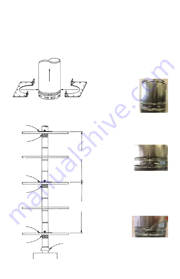
4. Mounting holes are provided around the
perimeter of the Firestop Support Plate. Use
appropriate fasteners to secure the Support
Plate halves to the opening between floors.
(Firestop Support Plates should be attached
to the TOP of the opening only (see Figure
36).
5. For installations with multiple supports,
an Adjustable Length Section of Type B Gas
Vent should be installed between each pair of
Fig. 36
Firestop
Support
Plate
Adjustable
Length
Section
Firestop
Support
Plate
Adjustable
Length
Section
Firestop
Support
Plate
Adjustable
Length
Section
Appliance
Draft Hood
30 Feet
Maximum
30 Feet
Maximum
BV GAS VENT JOINT METHOD -
10” TO 30”
2. Press down on pipe
all the way around
until you hear a snap-
in-place sound. The
pipes are now firmly
connected. See Step 2.
1. Line up seams of both
pipes (ensure UP ARROW
on label is pointing up or
away from the appliance).
See Step 1.
TO LOCK JOINT
TO UNLOCK JOINT
3. Pry out all lances
(teeth). Rotate joint
slightly while gently
pulling apart. See
Step 3.
Step 1
Step 2
Step 3
Fig. 35
locations where a support is used (see Figure
36). This allows the location of the pipe recess
to be in the proper position at each opening
where a support is to be used. The Adjustable
Length Section also provides relief for linear
thermal expansion. The Adjustable Length
Section should be positioned directly under
the vent pipe section that is being supported.


