background image

1

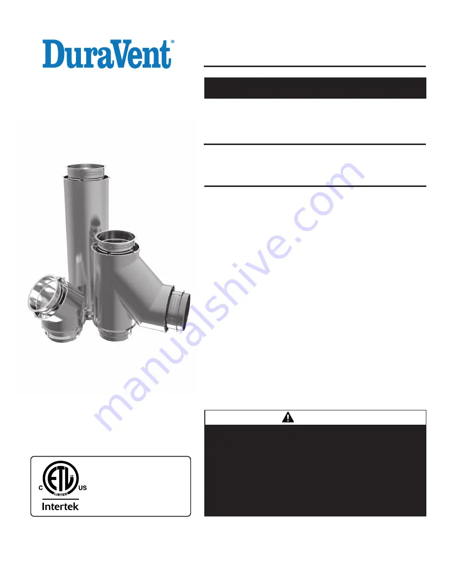
INSTALLATION

INSTRUCTIONS

1" air Double Wall for Special Gas Vent 
Category I, II, III, and IV Applications.

5” to 36” Diameter Vent for use on Positive, Neutral and Negative Pressures 
up to 35” W.C.

This installation manual will enable you to obtain a safe, efficient and dependable 

installation of this vent system. Please read and understand these instructions 

before beginning your installation.
Do not alter or modify the components of this chimney system under any circum-

stances. Any modification of alteration of the vent system or approved accesso-

ries, including but not limited to the appliance it is connected to, may void the 

warranty, listings and approvals of this system and could result in an unsafe and 

potentially dangerous installation.
A. Examine all components for possible shipping damage prior to installation.
B. Proper joint assembly is essential for a safe installation. Follow these 
     instructions exactly as written: Check severeness of joints upon completion of 

assembly.

C. This venting system must be free to expand and contract. This venting system 

must be supported in accordance with these instructions.

D. Check for unrestricted vent movement through walls, ceilings, and roof 
     penetrations.
E. Different manufacturers have different joint systems and adhesives. Do not mix 

pipe, fittings, or joining methods from different manufacturers.

    WARNINGS

FAILURE TO FOLLOW THESE INSTALLATION INSTRUCTIONS COULD CAUSE FIRE, 
CARBON MONOXIDE POISONING, OR DEATH. IF YOU ARE UNSURE OF INSTALLA-
TION REQUIREMENTS, CALL THE PHONE NUMBER LISTED ON THE BACK OF THESE 
INSTRUCTIONS.
A MAJOR CAUSE OF CHIMNEY RELATED FIRE IS FAILURE TO MAINTAIN REQUIRED 
CLEARANCES (AIR SPACES) TO COMBUSTIBLE MATERIALS. IT IS OF UTMOST IM-
PORTANCE THAT THIS VENT SYSTEM BE INSTALLED ONLY IN ACCORDANCE WITH 
THESE INSTRUCTIONS

PI  HYBRIDDAS1  L470 REV. 00  08-08-19

Listed to standards:

UL-1738

ULC-S636  Type ‘‘BH’’ vent

Report # 

SAVE THESE INSTRUCTIONS 

FOR FUTURE REFERENCE

MODEL DAS1-(BC) (5" TO 36")

Summary of Contents for DAS1

Page 1: ...stallation Follow these instructions exactly as written Check severeness of joints upon completion of assembly C This venting system must be free to expand and contract This venting system must be sup...

Page 2: ...TION FOR ALL MODEL DAS1 BC INTRODUCTION DAS1 BC double wall 5 TO 36 is a special stainless steel vent system for gas fired appliances listed as Category I II III and IV in USA UL 1738 or in Canada asT...

Page 3: ...in accordance with their respective instructions These parts which are installed in contact with wood or other combustibles are designed and tested to assure that they do not overheat at points of co...

Page 4: ...are designed for multiple venting Cat II III or IV appliances MAY NOT be common vented with Cat I natural draft appliances This limitation can be removed if an engineering analysis demonstrates norma...

Page 5: ...nchorPlate AP Fornon combustibleapplicationonly 5to 22 133 24to 36 82 AnchorPlatewithLength APL Fornon combustibleapplicationonly 5to 22 142 24to 36 87 AnchorPlateVentilated APV 5to 22 133 24to 36 82...

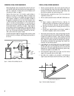
Page 6: ...t of more than 10 feet the stack must be supported by a Guy Section 3 TheventsystemmustterminatewithoneoftheDAS1 BC terminations Except a Category I appliances natural draft must use a Rain Cap It is...

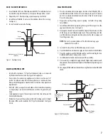
Page 7: ...WallThimble WT WTI Air gap or insulated Two half plate Termination Add sealant Opening dimension Table 5 for opening for all Models 2 Minimum overlap WALL PENETRATION 1 Prior to installation determin...

Page 8: ...t of the appliance 1 ADrainlength DL oraTeewithadrainteecap DTC isstronglyrecom mended Installthisdrainascloseaspossibletotheappliancefluecollar 2 A condensate drain is required for every 30 feet of h...

Page 9: ...8 LATERAL TEE BT88 DRAIN TEE CAP DTC DRAIN LINE By Others Trap Heigth must be equal to max appliance outlet Pressure Finishing Cone FC zzzz zzzzp z z z z zzzz frZZ ZZ 2j lZ ZZ ZZ zzzzzz V FIXED SUPPOR...

Page 10: ...s the value In theTable 7 8 use bracing or cable guying to stabilize chimney section above the roof See Figure 6 Figure 6 Height with rigid bracing or guying option for DAS1 BC Figure 7 Maximum freest...

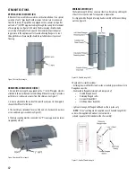
Page 11: ...ring on the Centering Flue Extension STEP 2 for HORIZONTAL installation only Only on Horizontal installation add a bead of blackViton caulking over the Viton O ring NOTE Sealant Caulking is supplied...

Page 12: ...to the inside of the inner flue adjacent to the nipple to channel the effluent to the drain 3 The duct drain is intended for use at the end of a horizontal run where access and drainage is needed see...

Page 13: ...he unflanged end of the tube should always point downward or towards downward slope Figure 12 Overlap Details forVariable Length INSTALLATION STEPS FORTHEVARIABLE LENGTH LV Step 1 Measure the distance...

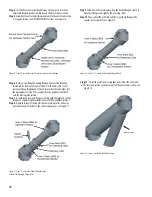
Page 14: ...regular length installation See JOINT ASSEMBLY section Step 8 Apply thin layer of sealant inside the retaining collar and also a continuous bead of sealant at the collar overlap seam See Figure 17 Fi...

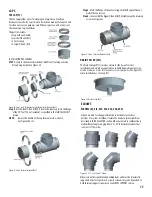
Page 15: ...be connected to a suitable disposable point It can also be used as an access for clean outs or access purposes See Figure 23 Same installation as aTee Cap TC ELBOWS ELBOWS E2 El5 E30 E43 E45 E88 E90...

Page 16: ...is used for a diameter change in duct system Uses when there is a sufficient length for duct run available for the size change TheTIN0 is used uses 2 of length per 1 increment diameter change TheTIN0...

Page 17: ...members are supplied by the installer See Figure 30 and 31 Figure 30 Ventilated Anchor Plate on a Framework Figure 31 Detail of theVentilated Anchor Plate on a Framework Supported duct sections in a v...

Page 18: ...art See Figure 34 35 36 for the three steps to install the DAS1 BC Figure 33 Ventilated Anchor Plate with Length APVL Figure 34 Step 1 of installation of APVL Figure 35 Step 2 of installation of APVL...

Page 19: ...crews of the flange band The Heavy DutyWall Support Assembly is bolted together with provided hardware It is made with adjustable struts which allows a variable clearance from the non combustible wall...

Page 20: ...hardware provided to form a rigid assembly NOTE Seal joint with S 375 sealant above and below support if exposed to weather Can be attached to combustible wall FULL ANGLE RING FAR A Full Angle Ring i...

Page 21: ...rtical position The inlet and outlet ends must each be supported TEE SUPPORT TheTees must be supported properly to protect them from bending It can be done by means of Anchor Plate AP Anchor Plate wit...

Page 22: ...ch 5 to 30 See Figure 49 Figure 47 Storm Collar Figure 48 Flashing Figure 49 Adjustable Flashing NOTE The flashings are non ventilated and does not provide for any reduced clearance to combustible INS...

Page 23: ...incorporates a drain hose from either a Drain length or a Drain tee cap the hose must be inspected periodically to ensure that water is in the trap loop If a proper trap loop is not maintained exhaus...

Page 24: ...08 08 19 DuraVent Limited reserves the right to make changes at any time without notice in design materials specifications prices Consult your local distributor for chimney system code information 10...

Reviews: