13
WARNING
A support must always be installed right above each
offset (two elbows) to support the chimney above the
offset.
OFFSET INSTALLATION CONT’D
5
ROOF SUPPORT (RS)
The Roof Support has three possible uses:
-It may be used to support a chimney from the
roof. It adjusts to any roof pitch.
-It may be used on a floor, ceiling or roof above an
offset to support the chimney above the offset.
-It may be used on a floor, ceiling or roof as a
supplementary support when the chimney height
exceeds that of the primary support.
INSTALLATION INSTRUCTIONS
With the chimney extending through the hole in the
roof, ceiling or floor and the radiation shield in place,
proceed as follows:
Step 1. Assemble the support collar to fit your chim-
ney diameter, as described on the instruction sheet
supplied with the support.
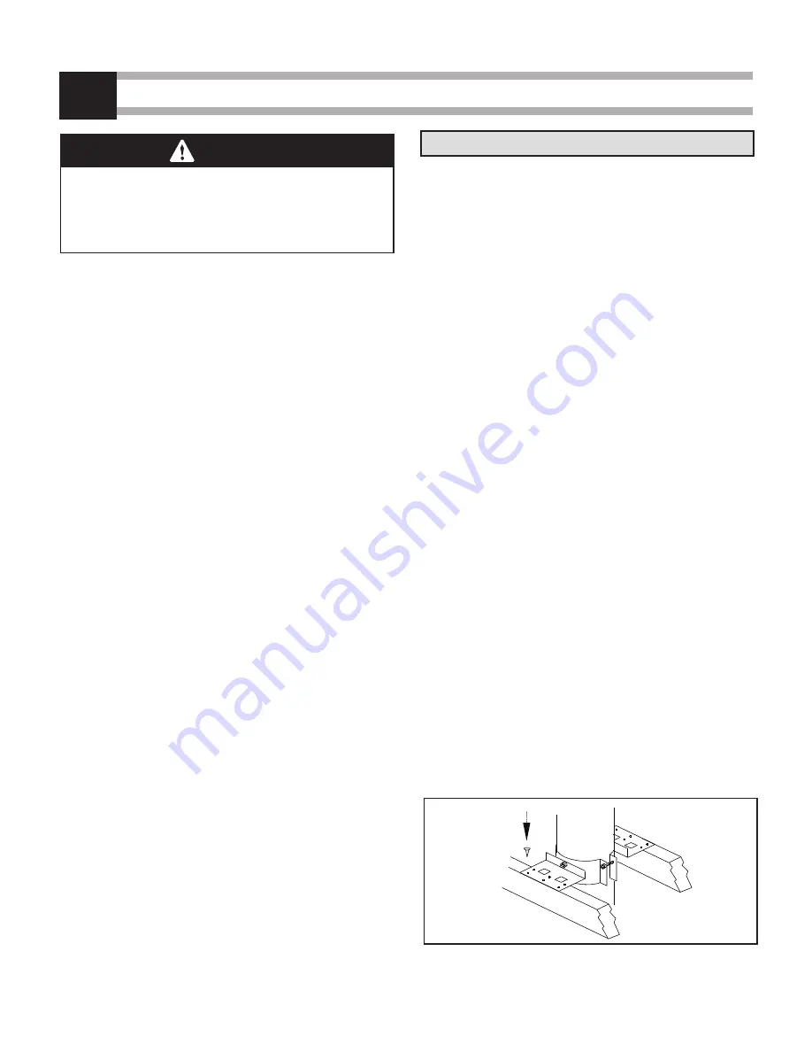
Step 2. Slip the support down over the chimney
length until its brackets rest on the roof or
floor. Tighten the collar around the chimney.
Step 3. Center the chimney and nail or screw the
support to the roof or floor using (8) - 2-1/2"
nails or (8) N°. 8 - 1-1/4" wood screws.
Step 4. Install the remaining chimney lengths, until
the required chimney height is reached.
Figure 14
INSTALLATION INSTRUCTIONS
Install the required support and the chimney as
described in the support’s installation instructions.
When you reach the height at which the elbow will
be installed, proceed as follows:
Step 1. Install the insulated offset elbow on the vertical
chimney length. Turn it in the required direction
and fasten it to the chimney with the (4) 1/2’’
metal screws provided.
Step 2. Place the required offset chimney length (see
Table 7 below) on the elbow. Turn it clockwise
to lock it in place.
Step 3. Use another elbow to turn the chimney ver-
tically. Again secure the elbow to the chimney
length using the (4) 1/2’’ metal screws provided.
Step 4. Install the remaining chimney as described in
the instructions for the Roof Support.
INSTALLATION CALCULATIONS
Determine the offset required in view of the obstacles
that must be avoided (see Figure 13). Refer to Table
7 to determine the elbows required as well as the
insulated length needed.


