7
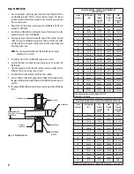
Figure 2- Vertical Installation Requirements
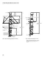
MAINTAIN PROPER SLOPE
• Install with a continuous 1/4” per foot (minimum) slope, as is required
by the National Fuel Gas Code for all gas-fired appliances.
• Vent systems for condensing appliances must have a continuous 1/4”
per foot (minimum) slope toward the appliance or a condensate drain.
Always check the appliance manufacturer’s instructions for proper drain
requirements.
• DuraSeal® offers a range of tees and elbows that are built incorporating
a 2 degree slope, we recommend that you use these to generate your
slope.
• Some appliances require the venting system to be sloped toward the
horizontal termination.
• Remember, if you raise the appliance or lower the ceiling you must adjust
the slope of the vent to maintain the 1/4” per foot minimum. See
Figure
5 & 26.
VERTICAL INSTALLATION REQUIREMENTS
1. The vent system must terminate at least 3 feet above the roof line and
at least 2 feet higher than any portion of the building within 10 feet.
See
Figure 2.
This limitation can be removed if an engineering analysis
demonstrates normal and safe operation of appliance.
2. When terminated at a height of more than 10 feet, the stack must be
supported by a Guy Section.
3. The vent system must terminate with one of the DuraSeal® terminations.
Except;
a) Category I appliances (natural draft) must use a Rain Cap. It is optional
on Category II. This limitation can be removed if an engineering
analysis demonstrates normal and safe operation of appliance.
b) Vent systems without provisions for draining rain water must use a
Rain Cap.
c) Terminations or approved mechanical vent devices specified or
provided by the appliance manufacturer are permitted.
4. The total continuous distance of the vent system from the appliance flue
collar to the termination shall not exceed that specified in the appliance
manufacturer’s installation instructions. When venting natural draft ap-
pliances the termination must be at least 5 feet above the topmost draft
hood. Otherwise a listed mechanical draft inducing device is required.
This limitation can be removed if an engineering analysis demonstrates
normal and safe operation of appliance.
5. In general, systems installed in cold climates perform best, and condensa-
tion is reduced, when the system is fully enclosed by some part of the
building structure or by using insulated DSID venting system.
6. In cold climates do not install a condensate drain on the exterior of the
building. Doing so may result in dangerous icy conditions on surfaces
near the drain and may cause damage to the vent system and/or the
building exterior. DuraVent will NOT be held liable for any personal injury
or property damage due to any formation of ice.
7. Vertical supports are required after every transition to vertical. Vertical
supports are also required after every offset elbow.
8. Unless DuraSeal is installed in a fire rated shaft, a roof thimble and support
is required when penetration fire rated floors, walls or ceilings.
2 ft. above structures within 10 ft.
10’
2’
ROOF / FLOOR PENETRATION
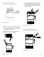
1. A roof thimble (RT) or roof thimble insulated (RTI) for cold climate must
be installed every time the vent system passes through a floor or roof.
2. Prepare the roof / floor by cutting a square opening. See
Table 9, 10 &
11.
3. Install the roof thimble. You may cut the radiation sleeve if it is too long.
See
Figure 3
.
4. For roof installation, install a flashing.
Support or Guide
Roof thimble
Opening dimension See Table 9,
10 & 11 for all Models
Air gap
or insulated
Flashing
Figure 3 - Roof penetration


