background image

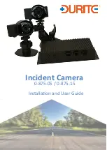
Incident


Camera 

Installation and User Guide


0-875-05 / 0-875-15

Summary of Contents for 0-875-05

Page 1: ...Incident Camera Installation and User Guide 0 875 05 0 875 15...

Page 2: ...d WiFi dongle OpDonal push buUon A second camera and extension cable may be provided according to speci caDon Important note Do not use any WiFi dongle with your Incident Camera main control unit othe...

Page 3: ...Incident Cam Installation User Guide General setup of 3 9...

Page 4: ...the control unit using the 20 pin connector This should click in with a rm press Locate suitable covert connecDon points to the vehicle s wiring and idenDfy the following sources A permanent 12V or 2...

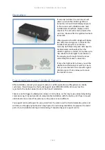
Page 5: ...s Connect each camera to its respecDve extension cable Cau8on ensure that the coloured wires which join pin match at the pins The end of the extension cable which connects to the camera is labelled wi...

Page 6: ...ideo quality should be checked and con rmed during the commissioning process Installing the panic buUon The small push buUon included with the kit funcDons as the system s panic buUon When pressed it...

Page 7: ...to commission your system Ensure that you are located in an area with a good 3G data signal If not endeavour to move the locaDon to one Commissioning your Incident Camera Amer installaDon contact your...

Page 8: ...e LEDs are not illuminated turn the vehicle s igniDon o and then wait ten minutes before conDnuing 4 When all LEDs are illuminated and steady leave the vehicle s engine running for at least one minute...

Page 9: ...e 32GB or 64GB NAND Flash Camera sensor 5 0MP opDonal infrared Night Vision Video 720p or 1080p resoluDon up to 30FPS 120 viewing angle Audio Dual mic DSP and advanced audio enhancement OperaDng tempe...

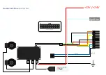
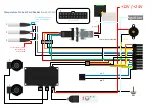
Page 10: ...ignition 12V 24V 1 2 Standard Installation Incident Cam pin 3 pin 1...

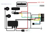
Page 11: ...ignition 12V 24V 1 2 Privacy Switch Incident Cam pin 12 pin 3 pin 1...

Page 12: ...ignition 12V 24V 1 2 Driver ID Incident Cam pin 17 pin 16 pin 11 pin 3 pin 1...

Page 13: ...ignition 12V 24V 1 2 Driver Feedback Incident Cam pin 3 pin 1 pin 13...

Page 14: ...V connector Leave black disconnected For last sensor in daisy chain leave red disconnected 1 2 3 For first sensor in daisy chain connect blue to black 1 2 Temperature Probe Card Reader Incident Cam pi...

Reviews: