
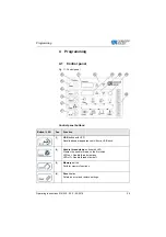
Programming
Operating Instructions 512/532 - 05.0 - 04/2018
35
4.8
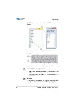
Changing the seam appearance
1.
Press the
Select
button until the
Pattern Number
symbol
LED illuminates.
2.
Press the
+/– Function
buttons until the desired seam appe-
arance number is shown in the
Function
display.
3.
Press the
Ready
button.
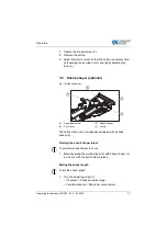
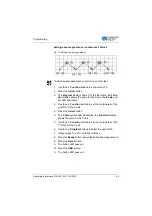
4.9
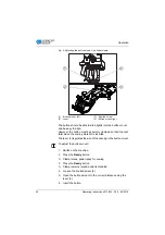
Bobbin winding
Prerequisite:
• Needle removed.
• Needle thread not threaded.
1.
Press the
Ready
button.
The button LED illuminates.
2.
Press the
Ready
button.
The button LED goes out.
3.
Press the
Select
button until the
Bobbin
symbol LED illumi-
nates.
4.
Press the
Ready
button.
The button LED illuminates, the clamp lowers.
5.
Press the pedal forwards.
The bobbin winding process starts.
6.
Press the pedal fully forwards to stop the bobbin winding pro-
cess.
7.
Press the
Ready
button.
The button LED goes out, the clamp raises.
Summary of Contents for 512/532
Page 1: ...Operating Instructions 512 532 ...
Page 6: ...Table of Contents 4 Operating Instructions 512 532 05 0 04 2018 ...
Page 16: ...Safety 14 Operating Instructions 512 532 05 0 04 2018 ...
Page 60: ...Programming 58 Operating Instructions 512 532 05 0 04 2018 ...
Page 70: ...Maintenance 68 Operating Instructions 512 532 05 0 04 2018 ...
Page 86: ...Decommissioning 84 Operating Instructions 512 532 05 0 04 2018 ...
Page 88: ...Disposal 86 Operating Instructions 512 532 05 0 04 2018 ...
Page 97: ...Appendix Operating Instructions 512 532 05 0 04 2018 95 11 Appendix ...
Page 98: ...Appendix 96 Operating Instructions 512 532 05 0 04 2018 ...
Page 99: ......


