Machine head
24
Service Instructions 745-35-10 D - 00.0 - 10/2017
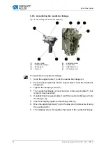
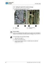
To remove switching cylinder and needle bar linkage:
1.
Remove needle bar linkage (7) (
2.
Remove the switching cylinder (6) used for the middle knife drive
(
Assembling the crank pin
Fig. 15: Assembling the crank pin
To assemble the crank pin:
1.
Loosen the fastening screws (
Caution
: Left-handed thread).
2.
Loosen the needle bar connecting rod from the crank pin (8) and pull
it off along with the needle cage.
3.
Turn the handwheel until the hexagon screws (14) are facing down.
In this position, the screws are accessible.
4.
Loosen the hexagon screws (14).
5.
Loosen the screw (9).
The screw can be accessed through the hole (3) (figure above).
(8)
- Crank pin
(9)
- Screw
(10) - Locating bore
(11) - Thread lever
(12) - Arm shaft
(13) - Gage
(14) - Hexagon screws
⑧
⑨
⑫
⑬
⑭
⑩
⑪
⑧
Summary of Contents for 745-35-10 D
Page 1: ...745 35 10 D Service Instructions...
Page 6: ...Table of Contents 4 Service Instructions 745 35 10 D 00 0 10 2017...
Page 10: ...About these instructions 8 Service Instructions 745 35 10 D 00 0 10 2017...
Page 74: ...Machine head 72 Service Instructions 745 35 10 D 00 0 10 2017...
Page 84: ...Transport carriage 82 Service Instructions 745 35 10 D 00 0 10 2017...
Page 116: ...Light barriers 114 Service Instructions 745 35 10 D 00 0 10 2017...
Page 122: ...Aligning the machine head 120 Service Instructions 745 35 10 D 00 0 10 2017...
Page 128: ...Folder 126 Service Instructions 745 35 10 D 00 0 10 2017...
Page 146: ...Throw over stacker 144 Service Instructions 745 35 10 D 00 0 10 2017...
Page 282: ...Programming 280 Service Instructions 745 35 10 D 00 0 10 2017...
Page 292: ...Maintenance 290 Service Instructions 745 35 10 D 00 0 10 2017...
Page 294: ...Decommissioning 292 Service Instructions 745 35 10 D 00 0 10 2017...
Page 296: ...Disposal 294 Service Instructions 745 35 10 D 00 0 10 2017...
Page 308: ...Troubleshooting 306 Service Instructions 745 35 10 D 00 0 10 2017...
Page 337: ......


