background image

Thread cutter

Service manual 567 classic - 01.0 - 10/2015

57

16 Thread cutter

16.1 Setting the height of the thread-pulling knife

The height of the thread-pulling knife is factory-set such that the 
distance (5) between the upper edge of the knife carrier (4) and the hook 
bearing screw-on surface (3) is 10.7+0.05 mm. Fine adjustment is made 
by means of washers between the knife carrier (4) and the thread-pulling 
knife (2).

When changing the knives make sure that you do not lose the washers.

Correct setting

The thread-pulling knife (2) pivots as close as possible above the hook 
and is at the same height as the counter-blade (1).

Cover

Throat plate slide (


3.3.5 Opening and closing the throat plate slide

page 13)

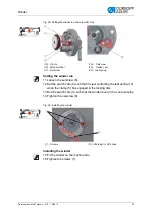
Fig. 48: Setting the height of the thread-pulling knife

WARNING

Risk of injury.

Risk of crushing injuries and stab wounds from mov-
ing and sharp parts. 

Switch the sewing machine off before you check 
and set the height of the thread-pulling knife.

6

4

1

2

3

5

(1) - Counter-blade
(2) - Thread-pulling knife
(3) - Hook bearing mounting surface

(4) - Thread-pulling knife
(5) - Distance
(6) - Screw

Summary of Contents for 567 CLASSIC

Page 1: ...567 classic Service manual...

Page 2: ...dler AG and protected by copyright Any reuse of these contents including extracts is prohibited without the prior written approval of D rkopp Adler AG Copyright D rkopp Adler AG 2015 IMPORTANT READ CA...

Page 3: ...sewing machine in place 16 3 6 Putting the handwheel into position 17 4 Setting the handwheel scale 19 5 Positioning the arm shaft 20 6 Positioning the toothed belt pulleys 21 6 1 Upper toothed belt...

Page 4: ...2 Setting the hook thread guide 56 16 Thread cutter 57 16 1 Setting the height of the thread pulling knife 57 16 2 Setting the cutoff curve 58 16 3 Setting the cutting pressure 60 16 4 Adjusting the n...

Page 5: ...in this manual is represented or highlighted by the fol lowing characters in order to facilitate easy and quick understanding Correct setting Indicates proper setting Malfunctions Specifies the fault...

Page 6: ...ys from the operator s point of view 1 3 Other documents This equipment includes components from other manufacturers Each manufacturer has performed a hazard assessment for these purchased parts and c...

Page 7: ...rts from suppliers observe the safety information and oper ating manual provided by the manufacturer All warnings on the machine must always be in legible condition and may not be removed Missing or d...

Page 8: ...used The power plug may only be connected to the power cable by a qualified specialist Work on live components and equipment is prohibited Exceptions are de fined in the specifications in DIN VDE 0105...

Page 9: ...hock Risk of puncturing Risk of crushing DANGER Type and source of risk Consequences of non observance Measures for avoiding the risk This is what a warning looks like for a hazard that will result in...

Page 10: ...hazard that could result in moderate or minor injury if the warn ing is ignored CAUTION Type and source of risk Measures for avoiding the risk This is a warning note for a hazard that could result in...

Page 11: ...mpaired in their ability to function correctly 1 Lay any excess cabling neatly in proper cable snakes 2 Tie the snakes together using a cable tie If possible bind the snakes to fixed parts The cables...

Page 12: ...t for that particular type of setting work 3 3 1 Access to the machine bottom section In order to access the components at the machine bottom section you must first tilt the machine upper section Fig...

Page 13: ...g the arm cover 1 Turn the adjusting wheel for the sewing foot stroke 3 to 2 2 Loosen the screws 1 3 Hold the arm cover 2 on the adjusting wheel and remove it Fitting the arm cover 1 Turn the adjustin...

Page 14: ...s 1 2 Remove the head cover 2 Fitting the head cover 1 Fit the head cover 2 2 Tighten the screws 1 3 3 4 Removing and fitting the valve cover Fig 4 Removing and fitting the valve cover Removing the va...

Page 15: ...ide Fig 5 Opening and closing the throat plate slide Opening the throat plate slide 1 Press the clamping spring 3 downwards 2 Push the throat plate slide 1 apart Closing the throat plate slide 1 Screw...

Page 16: ...ve the throat plate 2 Installing the throat plate 1 Insert the throat plate 2 ensuring that the nose 4 of the bobbin housing 3 is in the cutout of the throat plate 2 Tighten both screws 1 3 Close the...

Page 17: ...plate page 14 Important Check the feed dog position in its movement at maximum stitch length depending on the equipment 6 or 9 by turning on the handwheel The feed dog must have an even distance from...

Page 18: ...to be locked in place To do this the locking peg from the accessory pack is inserted into a groove on the arm shaft crank to block the arm shaft Fig 9 Locking peg and arresting grooves on the arm sha...

Page 19: ...Insert the locking peg 3 with the appropriate end in the groove 1 Removing the locking mechanism 1 Pull the locking peg 3 out of the groove 1 2 Insert the plug into the locking opening 2 3 6 Putting...

Page 20: ...Working basis 18 Service manual 567 classic 01 0 10 2015...

Page 21: ...l the first setscrew is under the opening 1 2 Release the setscrew through the opening 1 3 Turn the handwheel by 50 such that the second setscrew is under the opening 1 4 Release the setscrew through...

Page 22: ...m shaft crank Setting steps 1 Release all the setscrews 3 on the arm shaft crank 1 2 Turn the arm shaft crank 1 such that the setscrews 3 are seated flush on the flat of the arm shaft 3 Push the arm s...

Page 23: ...per toothed belt pulley are seated flush on the flat The distance between the winder wheel and the upper toothed belt wheel is 0 8 mm Cover Arm cover 3 3 2 Removing and fitting the arm cover page 11 F...

Page 24: ...ing ring or slipping off Cover Tilt the upper section 3 3 1 Access to the machine bottom section page 10 Fig 15 Setting the lower toothed belt pulley Setting steps 1 Using the screwdriver push the too...

Page 25: ...the stitch regulator gear The plates for the gear are paral lel the frame cannot be moved Cover Tilt the upper section 3 3 1 Access to the machine bottom section page 10 Setting steps 1 Switch off the...

Page 26: ...he shaft 4 and tighten it with a wrench 6 10 Screw down the stitch length adjusting wheel 1 using screw 2 11 Check whether the plates for the stitch regulator gear 8 are parallel to one another If the...

Page 27: ...rn the stitch length adjusting wheel clockwise as far as it will go The stitch length adjusting wheel can only be turned up to the maxi mum stitch length set Fig 18 Setting the stitch length limit Set...

Page 28: ...entric for the forward and backward stitches Correct setting The forward and backward stitches are the same length As a test sew a seam forwards stop and sew a seam backwards The insertions of the for...

Page 29: ...og Order First check the following setting Needle bar linkage 10 Aligning the needle bar linkage page 33 9 1 Setting the feed dog position Correct setting The feed dog is exactly in the center of the...

Page 30: ...d dog on the feed dog carrier Setting steps 1 Loosen the screws 3 2 Move the feed dog 1 on the feed dog carrier 2 such that the needle pierces exactly in the center of the needle hole for the feed dog...

Page 31: ...ings 2 5 Move the feed dog carrier cross line to the sewing direction such that the feed dog is exactly in the center of the throat plate cut out 6 Push the adjusting rings 2 toward each other as far...

Page 32: ...ing the pusher eccentric Correct setting Handwheel at the 190 position and set the stitch length adjusting wheel to the maximum stitch length If the drive is moved manually the feed dog stops Cover Ti...

Page 33: ...rrect setting Place the feed dog in the uppermost position by turning the handwheel The upper edge of the feed dog protrudes 0 5 mm above the throat plate Cover Tilt the upper section 3 3 1 Access to...

Page 34: ...es At 90 the feed dog is in the upward movement at 270 in the downward movement Cover Tilt the upper section 3 3 1 Access to the machine bottom section page 10 Fig 24 Setting the feed dog lift Setting...

Page 35: ...heel to 0 The needle pierces exactly in the center of the feed dog needle hole 10 1 Moving the needle bar linkage sideways Cover Arm cover 3 3 2 Removing and fitting the arm cover page 11 Head cover 3...

Page 36: ...sert the plugs in the openings 3 9 Tighten all 3 setscrews 2 10 Tighten the adjusting wheel for the sewing foot pressure 1 Order Then check the following settings Loop stroke position 11 2 Setting the...

Page 37: ...wheel to 0 Needle pierces in the center of the needle hole for the feed dog Setting steps 1 Position the stitch length adjusting wheel to 0 2 Loosen the setscrews 1 3 Align the needle in the center of...

Page 38: ...locked in place at position 1 page 16 Maximum 0 1 mm distance between the hook tip and the groove for the needle Cover Tilt the upper section 3 3 1 Access to the machine bottom section page 10 Throat...

Page 39: ...such that the distance between the hook tip 6 and the groove for the needle 5 is 0 1 mm at most without the hook tip 6 touching the needle 5 Tighten the screws 4 for the hook support 3 6 Check the lo...

Page 40: ...page 33 A straight and undamaged needle must be inserted Operating manual section Inserting and replacing the needle Correct setting Machine is locked in place at position 1 page 16 The hook tip 2 po...

Page 41: ...for the hook clamping ring 1 4 Turn the hook such that the hook tip 4 points exactly to the vertical center line of the needle 3 5 Tighten the setscrews 2 for the clamping ring 1 6 Remove the lock pa...

Page 42: ...n Inserting and replacing the needle Correct setting Machine locked in place at position 1 page 16 The needle guard pushes the needle just enough away so that it can not be touched by the hook tip Cov...

Page 43: ...Setting the needle bar height Order First check the following settings Loop stroke position 11 2 Setting the loop stroke position page 38 A straight and undamaged needle must be inserted Operating man...

Page 44: ...chine in place at position 1 page 16 2 Position the stitch length adjusting wheel to 0 3 Loosen the screw 2 for the needle bar 1 4 Move the height of the needle bar 1 such that the hook tip 4 is in th...

Page 45: ...in that position So that the thread can slip through without a problem the width of the lifting gap and the timing of opening have to be set Faults caused by an incorrect setting Thread breakage Forma...

Page 46: ...ng the lifting gap Setting steps 1 Loosen the screw 3 2 Push the cover 2 downwards 3 Loosen the setscrew 1 4 Set the spool housing lifter such that the gap between the nose of the spool housing and th...

Page 47: ...the middle of the opening insert hex key in the setscrew for orientation Cover Tilt the upper section 3 3 1 Access to the machine bottom section page 10 Fig 34 Setting the timing for lifting Setting...

Page 48: ...ting an even sewing foot stroke Correct setting For sewing foot stroke 3 the presser foot and feeding foot are raised by the same height Cover Arm cover 3 3 2 Removing and fitting the arm cover page 1...

Page 49: ...to the feed dog 4 Tighten the screw 3 13 2 Setting the stroke movement for the feeding foot For correct feed the stroke movement for the feeding foot must be aligned to the stroke movement for the fee...

Page 50: ...eeding foot and feed dog Cover Arm cover 3 3 2 Removing and fitting the arm cover page 11 Fig 38 Setting the point in time for when the feeding foot touches down Setting steps 1 Position the stitch le...

Page 51: ...Setting steps 1 Turn the adjusting wheel for the sewing foot pressure 1 Clockwise more pressure Counter clockwise less pressure 13 4 Setting the sewing foot lifting height When the pedal is pressed b...

Page 52: ...rm cover page 11 Fig 40 Setting the sewing foot lifting height Setting steps 1 Loosen the adjusting wheel for the sewing foot pressure 2 Loosen the setscrews 1 3 Turn the lever 1 to set the distance b...

Page 53: ...nsion for thin material low thread strengths Greater thread tension for thick material high thread strengths Correct setting The loop of the needle thread slides at low tension over the thickest point...

Page 54: ...er position of the thread lever up to the point when the needle eye plunges into the material being sewn Correct setting Basic setting The thread tensioning spring does not contact the stop un til the...

Page 55: ...e stop collar in doing so 4 Tighten the screw 4 15 Winder 15 1 Setting the winder Correct setting The winder wheel runs smoothly and without axial play The winding process will stop automatically when...

Page 56: ...filled bobbin onto the winder 5 Fold the winder lever 3 upwards as far as it will go to the thread Fig 44 Setting the winder spacing Setting the winder spacing 6 Turn the winder spindle 12 such that t...

Page 57: ...the leaf spring 10 when the clamp 5 has engaged in the locking disc 13 Set the switch cam 9 such that the winder lever 3 has no axial play 14 Tighten the setscrew 8 Fig 46 Installing the winder Instal...

Page 58: ...ad is wound on evenly over the entire width of the bobbin Cover Arm cover 3 3 2 Removing and fitting the arm cover page 11 Fig 47 Setting the hook thread guide Setting steps 1 Loosen the screw 1 2 Mov...

Page 59: ...ves make sure that you do not lose the washers Correct setting The thread pulling knife 2 pivots as close as possible above the hook and is at the same height as the counter blade 1 Cover Throat plate...

Page 60: ...1 The distance between the widest extent 6 of the control cam 4 and the roller 3 is 0 1 mm at most In resting position the circle mark on the cutting edge of the thread pulling knife is exactly next t...

Page 61: ...roller 3 7 Move the control cam 4 such that the distance between its widest extent 6 and the roller 3 is 0 1 mm at most 8 Tighten the setscrews 5 9 Loosen the clamping screw 8 on the actuating lever 7...

Page 62: ...d by an incorrect setting Increased knife wear when the pressure is too great Problems when sewing on if the hook thread clamp is too high Problems in cutting the thread Cover Throat plate slide 3 3 5...

Page 63: ...s being tightened 16 4 Adjusting the needle thread tension Correct setting The threads are cut when the thread lever is at the top dead center hand wheel position 60 Cover Tilt the upper section 3 3 1...

Page 64: ...n to 60 5 Push the control cam 3 to the left as far as it will go and against the clamping ring 2 6 Turn the control cam 3 such that the roller 1 runs up at the contour of control cam 3 and the widest...

Page 65: ...ain switch 2 Keep the P key 2 and Reset key 3 pressed down simultaneously and switch on the machine at the main power switch in doing so The display starts 3 Release the P key 2 and the reset key 3 Th...

Page 66: ...ews 1 10 Loosen the setscrew 3 11 Turn the potentiometer axle such that the left display shows 1 in the first instance and the relevant maximum speed next to it 12 Tighten the setscrew 3 without chang...

Page 67: ...the coupling has dis engaged they are no longer parallel Cover Tilt the upper section 3 3 1 Access to the machine bottom section page 10 Fig 55 Attaching the safety snap on coupling Setting steps 1 F...

Page 68: ...the disc on the setting slot 2 such that 8 Nm is reached for the torque To increase the force Turn in the direction To reduce the force Turn in the direction 3 Tighten the screw 1 WARNING Risk of inj...

Page 69: ...juries due to contact with oil Contact with oil can cause irritation rashes aller gies or skin injuries ALWAYS avoid long term contact with oil ALWAYS thoroughly wash the affected areas if con tact wi...

Page 70: ...Fig 57 Lubrication of the upper part of the machine Setting steps 1 Check the oil level indicator every day 2 If the oil level is below the minimum level marking 3 Pour oil through the refill opening...

Page 71: ...the machine bottom section page 10 Fig 58 Hook lubrication Setting steps 1 Check the oil level indicator every day 2 If the oil level is below the minimum level marking 2 Pour oil through the refill o...

Page 72: ...ge 13 Fig 59 Setting the hook lubrication Setting steps 1 Turn the screw 3 Turn counter clockwise more oil is released Turn clockwise less oil is released The released amount of oil does not change un...

Page 73: ...operating pressure Setting steps 1 Pull the adjustment knob 1 up 2 Turn the turning handle until the pressure indicator 2 indicates 6 bar clockwise to increase pressure counterclockwise to reduce pres...

Page 74: ...steps 1 Place the collection tray under the drain screw 3 2 Unscrew the drain screw 3 completely 3 Allow water to drain into the collection tray 4 Tighten the drain screw 3 WARNING Risk of injury Swi...

Page 75: ...ut the filter tray using benzine 6 Tighten the filter element 1 7 Tighten the water separator 2 8 Tighten the drain screw 3 WARNING Risk of injury Switch off the machine at the main power switch and d...

Page 76: ...te 3 Hook 2 Area around the needle 1 Cleaning steps 1 Dust and fiber residues must be removed with a compressed air gun or a brush WARNING Risk of injury Switch off the machine at the main power switc...

Page 77: ...compressed air gun 19 4 Checking the toothed belt The condition of the toothed belt must be checked once a month A damaged toothed belt must be replaced immediately WARNING Risk of injury Switch off...

Page 78: ...aintenance work 76 Service manual 567 classic 01 0 10 2015 Correct setting The toothed belt exhibits no cracks or fragile areas When pressed with a finger the toothed belt must yield no more than 10 m...

Page 79: ......

Page 80: ...er Str 190 33719 Bielefeld Germany Phone 49 0 521 925 00 E Mail service duerkopp adler com www duerkopp adler com Subject to design changes Printed in Germany D rkopp Adler AG Service Instructions 079...

Reviews: