


6.2
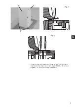
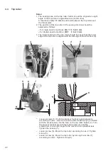
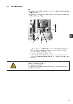
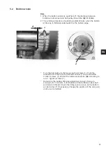
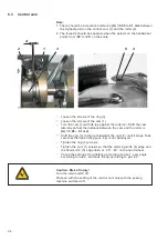
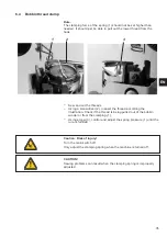
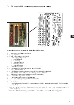
Starting position of the thread-pulling knife
Rule:
When the roller (1) is in the highest point of the control cam (2) the end
of the thread-pulling knife (3) should overrun the blade of the counter
knife (4) of
0.5-1 mm
.
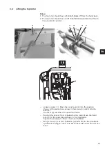
–
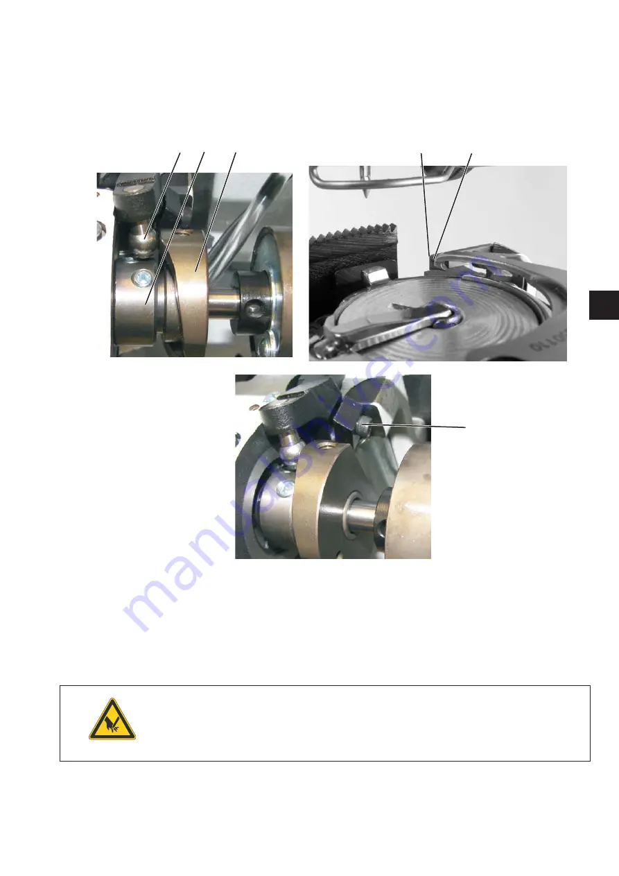
Check whether the control cam (2) butts against the ring (5).
–
Position the control cam according to the rule.
–
Loosen screw (6).
–
Set the thread-pulling knife (3) according to the rule.
–
Tighten screw (6).
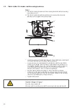
Caution: Danger of injury !
Turn the main switch off.
Proceed with the thread cutter setting only with the sewing
machine switched off.
33
EN
1
5
2
6
4
3