background image

Maintenance 

36

Operating Instructions 971 - 06.0 - 12/2020

5.2

Lubricating

For topping off the oil reservoir, use only lubricating oil 

DA 10

 or oil of 

equivalent quality with the following specifications:

• Viscosity at 40 °C: 10 mm²/s

• Flash point: 150 °C

You can order the lubricating oil from our sales offices using the following 
part numbers:

CAUTION

Risk of injury from contact with oil!

Oil can cause a rash if it comes into contact with 
skin.

Avoid skin contact with oil.


If oil has come into contact with your skin, wash the 
affected areas thoroughly.

NOTICE

Property damage from incorrect oil!

Incorrect oil types can result in damage to the machine.

Only use oil that complies with the data in the instructions.

CAUTION

Risk of environmental damage from old oil!

Incorrect handling of old oil can result in severe 
environmental damage.

ALWAYS observe the legally prescribed 
regulations for handling and disposal of mineral oil.

Take care to ensure that oil is NEVER spilled.

Container

Part number

250 ml

9047 000011

1 l

9047 000012

2 l

9047 000013

5 l

9047 000014

Summary of Contents for 971-01

Page 1: ...Operating Instructions 971 01...

Page 2: ...GmbH and protected by copyright Any reuse of these contents in cluding extracts is prohibited without the prior written approval of D rkopp Adler GmbH Copyright D rkopp Adler GmbH 2020 IMPORTANT READ...

Page 3: ...g the sewing head in and out 24 4 9 Swinging the cutting head in or out 25 4 10 Preparing starting and interrupting the automatic sequence 27 4 10 1 Replacing the adjustable material holders 27 4 10 2...

Page 4: ...king the direction of rotation 49 6 9 Pneumatic connection 50 6 9 1 Fitting the compressed air maintenance unit 50 6 9 2 Setting the operating pressure 50 7 Starting up for the first time 52 8 Decommi...

Page 5: ...he inst ructions Specifically chapter Operation S 17 is important for the operators Specialists This group has the appropriate technical training for performing maintenance or repairing malfunctions S...

Page 6: ...pecifies the work to be performed before or after a setting References Reference to another section in these instructions Safety Important warnings for the user of the machine are specifically marked...

Page 7: ...e Unauthorized modifications to the machine Use of untrained personnel Use of unapproved parts Transport D rkopp Adler cannot be held liable for breakage and transport damages Inspect the delivery imm...

Page 8: ...About these instructions 6 Operating Instructions 971 06 0 12 2020...

Page 9: ...could impair safety and damage the machine Only use original parts from the manufacturer Transport Use a lifting carriage or forklift to transport the machine Raise the machine max 20 mm and secure i...

Page 10: ...d in warnings Warnings in the text are distinguished by color bars The color scheme ba sed on the severity of the danger Signal words indicate the severity of the danger Signal words Signal words and...

Page 11: ...fatal injury if ignored This is what a warning looks like for a hazard that could result in moderate or minor injury if the warning is ignored Puncture Crushing Environmental damage Symbol Type of dan...

Page 12: ...vironmental damage if ignored This is what a warning looks like for a hazard that could result in pro perty damage if ignored CAUTION Type and source of danger Consequences of non compliance Measures...

Page 13: ...ts on the sewing head 1 1 Knurled screw for the sewing foot pres sure 2 Needle thread regulator 3 Needle thread monitor 4 Needle 5 Flap 6 Thread monitor 7 Oil level sight 8 Thread monitor LEDs 9 Guide...

Page 14: ...ull the magnetic roller down in order to swing the sewing head out 17 Magnet creates a magnetic field for the magnetic roller 18 Transport roll to set the correct needle thread quantity 1 Oil pot for...

Page 15: ...hine description Operating Instructions 971 06 0 12 2020 13 Fig 4 Elements on the cutting head 2 6 Blow pipe for the sewing material 7 Blow pipe for the chain 8 Bottom blade 9 Top blade 10 Sliding blo...

Page 16: ...Instructions 971 06 0 12 2020 3 3 Elements on the frame Fig 5 Elements on the frame 1 Compressed air gun 2 Pressure controller with pressure gage 3 Left pedal 4 Rotary knob for the speed of the tzurn...

Page 17: ...Machine description Operating Instructions 971 06 0 12 2020 15 3 4 Elements on the control box Fig 6 Elemente am Steuerkasten 1 Motor circuit breaker...

Page 18: ...stacker Fig 7 Elements on the stacker 1 Looper for sewing material transport 2 Connecting plate between the material holder and the rack of the stacker 3 Magazine receiving the material parts 4 Lever...

Page 19: ...bobbin thread reel Thread tension Setting the needle thread tension Setting the bobbin thread tension 4 2 Switching on the machine Fig 8 Switching on the machine To switch on the machine 1 Turn the ma...

Page 20: ...el holder 2 2 Guide the thread alternately through the guide eyelets of the take up arm 1 Fig 10 Threading the needle thrad 2 3 Feed the thread through the needle thread tensioner 5 and thread guides...

Page 21: ...l of thread on the thread reel holder 2 Guide the thread through the thread guide 1 3 Guide the thread top down through the right opening of the thread guide 2 4 Guide the thread top down through the...

Page 22: ...the thread down holder 14 from its latching For this purpose press the spring 10 to the back 11 Pull the thread through the holes 13 and 12 12 Placethethreadinfrontofthewireoftheremainingthreadmonito...

Page 23: ...through hole 16 19 Snap the thread down holder 14 shut 20 Close hatch 9 21 Insert cover plate 7 4 5 Adjusting the thread tensions The thread tension of the needle thread should be tighter than that o...

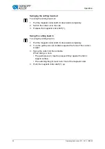
Page 24: ...on by turning the hand wheel 2 Swing the sewing head out For this purpose pull the magnetic roller downwards S 24 3 Thread the thread S 19 4 Swing the sewing head back in When doing so ensure that the...

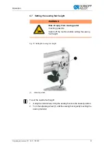
Page 25: ...o set the needle foot height 1 Using the hand wheel bring the sewing foot into the lowest position 2 Turn the adjusting wheel 1 until the sewing foot is gently touching the sewing material WARNING Ris...

Page 26: ...d out 1 Bring the needle to the upper position For this purpose turn the hand wheelagainsttherunningdirectionuntiltheneedleisoutofthematerial 2 Pull the magnetic roller shaft 1 downwards completely 3...

Page 27: ...2 of the throat plate insert 3 is pressed firmly against the fabric support surface that the switching flag 4 is behind the magnetic roller 4 Push the magnetic roller shaft 1 up 4 9 Swinging the cutt...

Page 28: ...ller shaft 1 Swing the cutting head in To swing the cutting head in 1 Pull the magnetic roller shaft 1 downwards completely 2 Turn the guide piece 2 clockwise against the force of the counter weight 3...

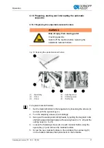
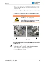
Page 29: ...ng out the sewing and cutting heads by pulling the magnetic roller shafts downward and swinging out the sewing head S 24 and the cutting head S 25 4 Loosen the fastening screws 6 on each material hold...

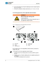
Page 30: ...djustable material holders you adjust the length of the cuff To change the size of the adjustable material holders 1 Release the lock by loosening screws 3 and 4 with the special key 1 2 Adjust the si...

Page 31: ...lders Fig 20 Adjusting the depth stop od the adjustable material holders By adjusting the depth stop of the adjustable material holders you adjusth the width of the cuff To adjust the depth stop of th...

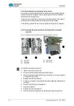
Page 32: ...Inserting the sewing material and starting the automatic sequence Fig 21 Inserting the sewing material and starting the automatic sequence To start the automatic sequence 1 Switch on the main switch 5...

Page 33: ...n if the cutting head and sewing head are run on the switch The turntable is turned counterclockwise The turntable activates switch S1 1 for the insertion position The turntable is switched off The cl...

Page 34: ...the sewing material The looper 2 moves upwards The rack 3 moves backwards With this movement the material is removed and thus conveyed into the magazine 4 The rack 3 moves upwards and to the front int...

Page 35: ...from sharp parts Punctures and cutting possible Prior to any maintenance work switch off the machine or set the machine to threading mode WARNING Risk of injury from moving parts Crushing possible Pr...

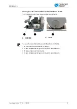
Page 36: ...rom flying particles Flying particles can enter the eyes causing injury Wear safety goggles Hold the compressed air gun so that the particles do not fly close to people Make sure no particles fly into...

Page 37: ...the side channel blower and the strainer in the ton To clean the side channel blower and the strainer in the ton 1 Disconnect the connections 1 and 2 2 Use a compressed air gun to remove lint accumul...

Page 38: ...with skin Avoid skin contact with oil If oil has come into contact with your skin wash the affected areas thoroughly NOTICE Property damage from incorrect oil Incorrect oil types can result in damage...

Page 39: ...If the oil can be seen at the lower edge the oil level is correct 3 If no oil is to be seen top up oil Topping up oil at the sewing head Fig 26 Topping up oil at the sewing head To top up oil at the...

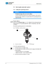
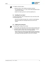
Page 40: ...Fig 27 Setting the operating pressure To set the operating pressure 1 Pull the pressure controller 1 up 2 Turn the pressure controller until the pressure gage 2 indicates the proper setting Increase p...

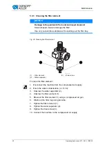
Page 41: ...a daily basis Fig 28 Draining the water condensation To drain water condensation 1 Disconnect the machine from the compressed air supply 2 Place the collection tray under the drain screw 3 3 Unscrew t...

Page 42: ...rew the filter element 1 5 Blow out the filter element 1 using a compressed air gun 6 Wash out the filter tray using benzine 7 Tighten the filter element 1 8 Tighten the water separator 2 9 Tighten th...

Page 43: ...Maintenance Operating Instructions 971 06 0 12 2020 41 5 4 Parts list A parts list can be ordered from D rkopp Adler Or visit our website for fur ther information at www duerkopp adler com...

Page 44: ...Maintenance 42 Operating Instructions 971 06 0 12 2020...

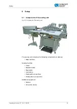
Page 45: ...ing unit Fig 30 Components of the sewing unit The sewing unit comprises the following components on delivery Base machine Sewing machine Cutter Material holder Reel stand Control box Pedal with foot s...

Page 46: ...ht and the cutting head height To adjust the sewing head heigth and the cutting head heigth 1 Loosen the screws 1 2 Twist the bolt 2 until the sewing head and the cutting head are in the desired heigh...

Page 47: ...ote Insert the reel stand and tighten the nut under the retaining plate Reel stand holder and unwinding bracket must be above one another 6 5 Aligning the sewing unit Correctly align the sewing unit a...

Page 48: ...g waste into the ton To connect the side channel blower 1 Plug the hose 5 into the connection of the cover 1 under which is NOT the strainer 2 Plugthehose 2 fromtheconnectionofthecover 1 WITHthestrain...

Page 49: ...sewing unit and guide the fastening rail 2 into the bracket 3 Set the clamping lever 1 Adjusting the height of the stacker Fig 35 Adjusting the heigt of the stacker To adjust the height of the stacker...

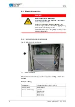
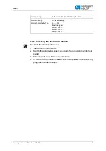
Page 50: ...om electricity Unprotected contact with electricity can result in serious injuries or death Work on the electrical system must ONLY be carried out by qualified electricians or appropriately trained an...

Page 51: ...automatic sequence on and off again using the right foot pedal 3 The turntable must turn counterclockwise 4 If the direction of rotation is NOT correct two phases in the connecting plug must be inter...

Page 52: ...by more than 0 5 bar NOTICE Property damage from oily compressed air Oil particles in the compressed air can cause malfunctions of the machine and soil the sewing material Ensure that no oil particle...

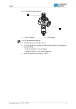
Page 53: ...the operating pressure 1 Pull the pressure controller 1 up 2 Turn the pressure controller until the pressure gage 2 indicates the proper setting Increase pressure turn clockwise Reduce pressure turn...

Page 54: ...orking properly Starting sewing for the first time 1 Start and stop the automatic sequence if a material holder is in front of the sewing head 2 Thread the needle and hook threads 3 Place the sewing m...

Page 55: ...ual oil from the oil pan under the fabric support surface using a cloth 5 Cover the control panel to protect it from soiling 6 Covertheentiremachineifpossibletoprotectitfromsoilinganddamage Observe th...

Page 56: ...Decommissioning 54 Operating Instructions 971 06 0 12 2020...

Page 57: ...national regulations When disposing of the machine be aware that it consists of a range of different materials steel plastic electronic components etc Observe the applicable national regulations for d...

Page 58: ...Disposal 56 Operating Instructions 971 06 0 12 2020...

Page 59: ...adler com 10 2 Errors in sewing process Meaning Possible causes Remedial action Knife does not cut properly Knife pressure is too high or too low Check knife pressure Sewing material is not held down...

Page 60: ...heck the thread tensions Operating Instructions Operation Sewing material is not held cor rectly Check the clamping pressure S 38 Sewing material is not spread or is insufficiently spread Check the sp...

Page 61: ...ce the needle Insert the needle into the needle bar Thread used is unsuitable Use the recommended thread S 4 Thread tensions are too tight for the thread used Check the thread tensions Operating Instr...

Page 62: ...Troubleshooting 60 Operating Instructions 971 06 0 12 2020...

Page 63: ...justed steplessly and can be adapted to the relevant requirements The double chain stitch sewing head of the 971 01 is fitted with a needle and looper thread monitor which stops the sewing machine aut...

Page 64: ...2 2020 cutting head The cutting distance can be changed using corresponding part sets To remove cutting waste suction systems with one sided or two sided suction are available The corresponding air co...

Page 65: ...8 4 1 4 84 1 9 6 6 8 9 8 4 6 2 A A 1 8 8 8 8 8 8 8 8 A A 1 9 8 8 8 BCC BCC BCC 2 D 1 4E 1 2 2 1 2 8 2 8 D 1 4E 8 2 A 2 2 8 8 8 8 8 D E 2 2 D E 8 D6E 2 8 8 1 1 D 1 4E 6 2 8 8 1 4 A 6 8 6 D6 E 8 D 1 4E...

Page 66: ...1 3 1 3 1 3 1 3 1 3 1 8 8 B B B B B B B B B B B B B B B C C 3 3 D 3 2 3 3 3 3 3 D B 3 2 3 3 5 E 6 A 8 5 E 6 A A 5 E 6 A 5 E 6 A 5 E 6 A 5 E 6 A 5 6 5 6 F 2 5 6 5 6 2 D 5 E 6 A A 5 E 6 A G3 5 E 6 A 5...

Page 67: ...12 2020 65 0 1 1 1 1 1 1 2 2 3 4 2 2 3 3 5 5 3 6 6 2 2 2 3 6 2 7 7 8 7 9 3 7 9 3 8 7 6 6 6 8 6 8 1 A A A A 3 3 B C D 1 1 3 3 E 6F E 6F B E 6F C D 1 1 3 3 1 1 1 1 1 1 C D 1 1 1 3 3 3 3 3 G 3 2 G 4 2 E...

Page 68: ...Appendix 66 Operating Instructions 971 06 0 12 2020 0 1 2 3 0 0 4 0 4 0 5 6 0 7 5 7 7 7 8 9 8 9 6 6 6 6 6 7 7 7 7 7 3 7 4 0 3...

Page 69: ......
Page 70: ...GERMANY Phone 49 0 521 925 00 E mail service duerkopp adler com www duerkopp adler com Subject to design changes Part of the machines shown with additional equipment Printed in Germany D rkopp Adler...

Reviews: