


966
1115,44
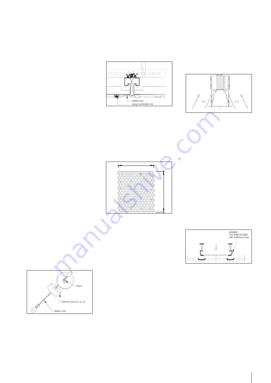
Beispielanordnung Magnete Standardelemente
5
© durlum GmbH | www.durlum.com | Subject to changes of dimensions and design. Errors reserved. All rights reserved. | Issued: 08.11.2016
4. When assembling the LOOP
®
elements,
the safety rope is screwed to the LOOP
®
element by means of a wing nut.
5. Measure the position of the LOOP
®
element exactly using the laser (longi-
tudinal and transverse rows). Hold the
LOOP
®
element with the rear magnet
(20 pieces per standard element) from
below horizontally against the ceiling
S7 KS (friction force by magnet). For
the arrangement of the magnets, see
below. To simplify assembly/disassem-
bly, the magnets can be glued to the
LOOP
®
element (e.g. LOCTITE).
6. The installation is then performed with
further elements similar to a puzzle.
The elements are to be aligned by sli-
ding them. To do so, the joints of the
LOOP
®
ceiling are aligned horizontally
by pushing or pulling the adjacent ele-
ment. Check the joint between the ele-
ments for flatness and uniform width.
7. For connection to the wall, the ele-
ments can be simply adapted to the
room, using a jigsaw. The cutting edge
is covered with a bracket or a plaster-
board frieze. In the area of the glass
wall, the cut is not covered. Ensure
clean cut.
MOUNTING OF LUMINAIRES
Note:
Mounting and electrical connection of the
luminaire must be performed by an autho-
rised skilled electrician (e.g. electric instal-
ler) in accordance with VDE 0100, taking
into account the technical information
and the legal regulations in force in your
country.
Safe operation of the luminaire is only gua-
ranteed if these instructions are observed.
This is why the mounting instructions should
be kept in a safe place. The manufacturer
cannot assume any liability whatsoever if
the instructions given below are not follo-
wed or the luminaire is used improperly.
1. Remove both springs of the
PUNTEO
®
-J85 LED downlight.
2. When fitting PUNTEO
®
-J85 LED down-
lights, a connecting adapter PUN J085-
018-Z001 is required, which is glued
centrally to the back of the element.
Attention: luminaires cannot be moun-
ted in the area of the secondary pro-
files!
3. Mount ballasts/drivers in the ceiling vo-
id, possibly on U 1040.
4. Perform electrical connection of the
driver.
5. Ensure that the LOOP
®
elements are
clean and free of grease. To fasten
the adapter PUN J085-018-Z001 to the
LOOP
®
element, a primer is required.
Note: The primer is not included in the
delivery. A primer for non-absorbent
substrates, e.g. EVT Primer MK, should
be used. Attach primer to the back of
the LOOP
®
in the glued area. Remove
the paper from the adhesive tape of
the LOOP
®
adapter PUN J085-018-Z001.
Then position and mount the adapter
on the back of the LOOP
®
element.
Press the adapter down firmly.
INSTALLATION MANUAL
LOOP
®
TYPE 3
ABBREVIATIONS
AH: Distance of the suspension hangers in
axial direction of the primary profile
AP: Distance of primary profiles U 1040
AS: Distance of secondary profiles W 2053-
ST
ASSEMBLY OF THE FALSE CEILING
Note:
Please take the S7 KS System Assembly in-
structions into account. With the following
exceptions:
Distannce of the primary profile <=800mm
Assembly of the suspension
Items 1-19 acc. to assembly instructions
Item 20
Cut the rail channel W 2053-ST to the requi-
red length.
Item 21
At the crossing points to the primary profi-
le, the rail channel W 2053-ST is screwed to
the L-shaped primary carrier U 1040 using a
self-securing screw connection M6.
Item 22
The joint formation of the rail channel is
performed using the rail channel connec-
tor W 2053-ST V.
Items 23 and 24 are withdrawn
ASSEMBLY OF LOOP
®
ELEMENTS
1. Wear clean cotton gloves.
2. Preassemble the safety ropes (min. 2 pi-
eces per standard element) as shown
on the drawing. Run rope through the
damper disc and safety rope anchor
disc and secure it in the armature disc
by bending the web.
3. Then run the preassembled rope
through an elongated hole (in the
area of the later fastening points of the
safety rope) in the rail channel out of
the ceiling void downwards.


