background image

- 19 -

D W E L L   C Y L I N D E R   P R O B L E M S
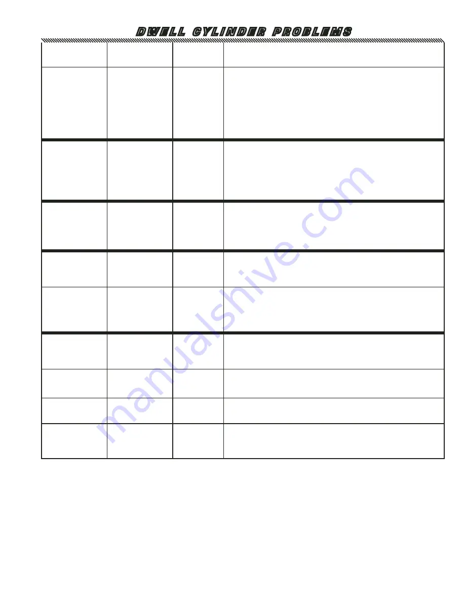
SYMPTOM

CORRECT 

FUNCTION 

INDICATOR

POSSIBLE

PROBLEM

ACTION

Dwell  cylinder  does     

not 

retract and 

weld stays on.

 Initiate, Weld 

timer, Feed 

reed switch, 

Dwell solenoid 

and Weld signal 

indicators 

are all on 

Constantly.

All lights flash in 

sequence

Weld timer.

Remove the push-on connector from terminal #4 of the Weld timer. If Dwell 

cylinder retracts and weld turns off replace Weld timer.

Dwell cylinder does 

not retract and 

weld stays on.

 Initiate, Dwell 

solenoid and 

Weld signal 

indicators 

are all on 

constantly.

All lights flash in 

sequence

Short cycle 

relay.

Test for voltage (24VAC+/-) at terminals #17 and #19. If the voltage is 

present return to the step up above. If the voltage is not present, 

now check the voltage (24VAC+/-) at the terminals #9 to #24, #18 

to #22 and #17 to #22. If the voltage is present all the time on these 

terminals replace the Short cycle relay.

Dwell cylinder does

    not retract.

Dwell solenoid 

and Dwell delay 

indicators are 

on constantly.

Dwell solenoid 

indicator goes 

on and off with 

every cycle. 

Stays on 150ms 

longer than feed 

reed indicator.

Dwell Delay 

timer.

Remove the push-on connector from terminal #4 of the Dwell Delay timer. 

If Dwell cylinder retracts replace the Dwell Delay timer.

Dwell cylinder does 

not retract.

 All indicators are 

functioning 

correctly

All lights flash in 

sequence

(A) Dwell 

solenoid.

(A) Turn the power off. (If the Dwell cylinder shaft retracts recheck symp-

tom).  Now try and lift the cylinder shaft up. If the cylinder shaft cannot 

be lifted replace the Dwell solenoid.

(B) Dwell 

cylinder.

(B) If the cylinder shaft can be lifted easily check the Dwell cylinder and 

air lines for air leaks. Turn the air off and then move the cylinder shaft 

up and down. If the cylinder shaft moves up and down without any air 

resistance the seals in the cylinder are most likely bad. Replace the 

Dwell cylinder. If a slight air resistance is present on the up and down 

motion replace the Dwell solenoid.

Sluggish movement 

of the Welding tip.

All indicators are 

functioning 

correctly

All lights flash in 

sequence

(A) Main air 

regulator.

A) Adjust main air regulator (80psi).     

(B) Air lines 

and 

Adjustable 

mufflers.

(B) Check air lines for leaks or water in the air lines. If there is water in 

the air lines, disconnect and blow out air lines. Remove and clean out 

adjustable mufflers. Reconnect air lines and adjustable mufflers.

(C) Dwell 

cylinder.

(C) Turn the power and air off. Check the Dwell Cylinder shaft for binding by 

moving shaft in and out of the cylinder. A slight air resistance should be 

present when the shaft is being moved in and out of the Cylinder.

(D) Dwell 

solenoid

(D) If the above procedures check out and the Dwell cylinder still has 

sluggish movement the problem maybe the Dwell solenoid. Remove the 

air line from air inlet of the solenoid and spray a light oil in the solenoid. 

Reconnect air line and cycle machine. If Dwell cylinder still has sluggish 

movement replace the Dwell solenoid.

Summary of Contents for 14000

Page 1: ... 1 OWNER S MANUAL AUTOMATIC BULK FEED PINSPOTTER M A C H I I MACH I MACH II MACH I MACH II MACHINERY DIVISION Owner s Manual for Mach I SN 4000 to 40111 Mach II SN 41000 to 41043 Approx May 03 to Feb 05 ...

Page 2: ...NTY Duro Dyne Machinery is manufactured by skilled mechanics utilizing the latest production techniques Each unit has been rigorously tested prior to packaging and shipment in order to ensure trouble free operation Your Duro Dyne machine has a two year warranty against defects in material Any component found to be defective will be repaired or replaced at the manufacturer s discretion at no cost i...

Page 3: ...44013 Feed Channel Spacer 17339 Vibrator Base 44001 Vibrator Sensor Cord 44002 Vibrator Sensor 44003 Vibrator Sensor Bracket 44008 Upper Feed Track 44016 Power Bar 44056 Upper Dwell Cylinder Bracket 17359 Bracket Insulator 44009 Upper Track Side Rails 44011 Lower Track Side Rails 44010 Lower Feed Track Casting 44017 Weld Cable 17394 Short Shaft Extension 17203 Fiber Insulator 17190 Replacement Pla...

Page 4: ...Dwell Cover 44044 Feed Cover 17377 Air Regulator 17372 Footswitch 44023 Control Module 44046 Component Module 44035 MACH I Power Pack 44036 MACH II Power Pack 44037 Power Pack Cover PARTS LOCATION FRAME ASSEMBLY ...

Page 5: ... 5 44041 Line Cord 44042 Line Cord Strain Relief Not Shown 44040 Mach II Weld Transformer 44019 Weld Cable Camlock 17327 Footswitch Receptacle PARTS LOCATION 44036 MACH II POWER PACK ...

Page 6: ... 6 PARTS LOCATION 44035 MACH I POWER PACK 17209 Line Cord 17210 Strain Relief 44038 Mach I Right Transformer 44039 Mach I Left Transformer 17327 Footswitch Receptacle ...

Page 7: ...4030 Troubleshooting Display Board 44008 Upper Feed Track 44031 Vibrator Potentiometer 44027 Knob 44032 Vibrator Lamp 44033 Vibrator Power Switch 44034 Weld Lamp 44010 Lower Feed Track Casting 44018 Weld Cable Retainer Block 17333 Vibrator Speed Control Located Inside Control Module 17256 Vibrator Socket 44006 Vibrator Socket Guard 44007 Vibrator Circuit Breaker 44027 Knob ...

Page 8: ... Dwell Solenoid 17359 Bracket Insulator 44057 Lower Dwell Cylinder Bracket 17325 Pressure Switch 39353 Anti Friction Strip 44010 Lower Feed Track Casting 44096 Upper Dwell Cylinder Bracket 17363 First Pulse Reed Switch not shown 44020 Head Terminal Strip 17356 Adjustable Muffler 17363 Feed Reed Switch PARTS LOCATION HEAD FEED ASSEMBLY ...

Page 9: ...Timer 44049 Track Sensor Relay 44051 Relay Board 17323 First Pulse Relay 17222 Terminal Strip Low Voltage 44091 24V Multi Tap Transformer 44052 12 Volt DC Power Supply 44048 Terminal Strip High Voltage 44047 Power Contactor 17310 24 Volt Transformer 44053 Weld Relay 17318 Feed Timer 44054 Heat Sink 44050 Track Sensor Relay Base ...

Page 10: ...upply line to the power pack pigtail should be 8 or heavier wire to minimize voltage losses The black and white wires are the power the green is ground 1b For the Mach II Connect the power pack to a source of 208 230 V 100 Amp power This service should be connected to a 60 amp disconnect box fitted with 60 amp slow blow fuses The power supply line to the power pack pigtail should be 6 or heavier w...

Page 11: ...or reference only and have no relationship with actual time It is recommended that an initial setting of 150 be used and then adjust up or down accordingly in reference to the quality of welds Weld time is the length of time the welding transformers are on A fraction of a second is generally all the time needed for a quality weld Unnecessary weld time not only wastes energy but can also burn up th...

Page 12: ...ibutor 3 Depending on usage and maintenance the up per welding tip plate will have to be periodically replaced The replacement weld tip plates can be ordered from your local distributor To replace the upper weld tip loosen the locking cap screw and remove the weld tip Remove the plate by loosening three 3 brass screws Throw away the screws and attach the new plate to the tip using three brass scre...

Page 13: ... 13 WIRING DIAGRAM FG MACH I ...

Page 14: ... 14 WIRING DIAGRAM FG MACH II ...

Page 15: ...s weld to bare metal but can easily be removed 3 Pins weld to bare metal but remain on the weld tip as it retracts 4 The pins do not weld at all Before troubleshooting always check 1 Air pressure for a minimum of 80 PSI during usage of unit 2 The input Voltage for a minimum of 208V and a maximum of 230V 3 The Weld Timer is set properly 4 The Upper and the Lower Weld tips for extreme wear It may be...

Page 16: ... indicators are functioning F e e d r e e d s w i t c h indicator is not functioning Feed reed switch indicator goes on and off with every cycle Feed reed switch The feed reed switch is a safety that will not allow the machine to operate if feed cylinder has not fully retracted To test the feed reed switch jump terminals 14 to 19 or 35 to 36 Now try to cycle the machine with this jumper in place I...

Page 17: ...is voltage is present now check the voltage 24VAC at the terminals 4 and 5 Terminals 4 and 5 should go from 24VAC to 0 and back to 24VAC with every cycle If this is correct the Dwell reed switch is functioning properly If the voltage reading is incorrect check the Dwell reed switch position To check the Dwell reed switch position first loosen the reed switch setscrews Slide the reed switch down an...

Page 18: ... the air lines disconnect and blow out all air lines Remove and clean muffler Reconnect the air lines and the muffler C Feed cylinder C Turn the power and air off Check the Feed cylinder and the Pusher with Pawl for binding Move Feed in and out The Feed should move in and out with a slight resistance D Feed Solenoid D If the above procedures check out and the Feed still has sluggish movement the p...

Page 19: ...well solenoid A Turn the power off If the Dwell cylinder shaft retracts recheck symp tom Now try and lift the cylinder shaft up If the cylinder shaft cannot be lifted replace the Dwell solenoid B Dwell cylinder B If the cylinder shaft can be lifted easily check the Dwell cylinder and air lines for air leaks Turn the air off and then move the cylinder shaft up and down If the cylinder shaft moves u...

Page 20: ...oltage at the terminals L1 and T1 on the Solid State Relays They should go from 208 230 VAC to 0 and back to 208 230 VAC every time the machine cycles Now test the secondary output voltage Place meter leads on copper bars coming out of the transformer s and test the voltage every time the machine is cycled The Mach 1 Transformers should read approximately 5VAC 2 5 VAC x 2 5VAC The Mach 2 should re...

Page 21: ...trol Relay Old Style E Vibrator Control Relay Board New Style To check the Vibrator Control Relay test the voltage 24VAC at terminals 2 and 5 new style or 13 and 14 old style There should be 24VAC at these terminals when there is no Weld Pin at the Track Sensor If this reading is correct Track Sensor now check the voltage 208 230VAC at terminals 1 and 11 new style or 6 and 7 old style at the relay...

Page 22: ...4003 Vibrator sensor bracket 44004 Vibrator Line Cord 44005 Vibrator socket 44006 Vibrator socket guard 44007 Vibrator fuse and bracket 44008 Upper feed track casting 44009 Upper track side rails 44010 Lower track casting 44011 Lower track side rails 44012 Anti friction strip 44013 Feed Channel Spacer 44014 Feed solenoid 44015 Dwell Solenoid 44016 Power bar 44017 Weld cable 44018 Weld cable retain...

Reviews: