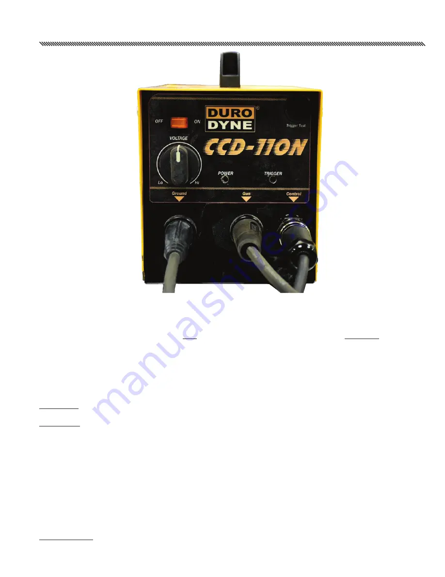
FRONT PANEL CONTROLS
FRONT PANEL CONTROLS
POWER SWITCH: The POWER switch applies AC voltage to the power supply Hi/Lo causing the weld capacitors
to charge to a voltage level determined by the setting of the VOLTAGE CONTROL. Also, the charge time is
dependent on the setting of the VOLTAGE CONTROL, ranging from 1 to 3 seconds.
When the POWER switch is placed in the OFF position, the weld capacitors will begin to discharge and continue
until the charge voltage reaches zero. The discharge time will vary depending on the setting of the VOLTAGE
CONTROL, the maximum time to discharge to the minimum of 0 on the VOLTAGE dial is about 6 seconds.
VOLTAGE CONTROL: This control sets the voltage level that the weld capacitors will charge to. Because the
charge circuitry is electronically regulated, this voltage is completely independent of any variation due to AC
input line voltage variations.
To increase the WELD VOLTAGE level, it is only necessary to rotate the control (Hi/Lo) to a higher setting.
To decrease the WELD VOLTAGE level, it is necessary to switch the POWER switch off as described above. After
the VOLTAGE CONTROL is reduced to the desired lower voltage, place the POWER switch in the off position
for about 6 to 10 seconds before switching back on.
NOTE: If this procedure is not followed, the weld capacitors will not be discharged to the lower level until after
the next weld. This will give the impression that there has been no change in the voltage level.
CIRCUIT BREAKER: This is primarily intended to protect the power supply from fire in the event of an internal
short circuit. On occasion, depending on room temperature and frequency of usage, this breaker may actuate.
If this should happen, shut the POWER switch off and wait about one minute before resetting the breaker. If
this problem should continue with frequency, stop and call for service.
POWER LIGHT: This indicator is probably the easiest to recognize, indicating when the power supply is on.
TRIGGER LED: This light will turn on when weld gun trigger is depressed.
-7-
Summary of Contents for 27122
Page 1: ...OWNER S OWNER S MANUAL MANUAL CCD110N CCD110N CCD110N PINSPOTTER 27122 ...
Page 14: ...NOTES ...
Page 15: ...NOTES ...


