- 10 -
OPERATION
Mach I and Mach II INITIAL ADJUSTMENTS
1)
Turn the power switch to “ON”.
2)
Turn the vibrator switch to “ON”.
3)
Add the weld pins to the hopper (vibrator bowl).
4)
Adjust the vibrator speed so that the weld pins climb the spiral track inside the vibrator bowl without
vibrating off.
5)
When the weld pins fill the track up to the proximity track sensor, the vibrator automatically shuts off.
6)
Flip the head test switch to either the “WELD #1” or “WELD #2” position.
NOTE:
Your Mach I and Mach II Pinspotter has two redundant weld circuits. In the event that the solid state
relay controlling the weld fails you may simply flip the switch to the other circuit and continue production.
A replacement Weld Relay should then be ordered through your local Duro Dyne wholesaler.
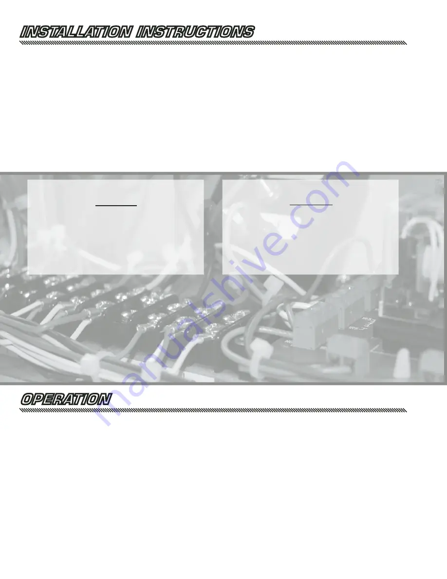
INSTALLATION INSTRUCTIONS
1a) For the Mach I -
Connect the power pack to a source of 208-230 V 30 Amp. power. The power supply line to the power
pack pigtail should be #8 (or heavier) wire to minimize voltage losses. The black and white wires are the
power, the green is ground.
1b) For the Mach II -
Connect the power pack to a source of 208-230 V 100 Amp. power. This service should be connected
to a 60 amp disconnect box fitted with 60 amp slow blow fuses. The power supply line to the power pack
pigtail should be #6 (or heavier) wire to minimize voltage losses. The black and white wires are the power,
the green is ground.
2)
Attach the foot switch to the foot switch socket on the rear of the power pack.
3)
Connect the air line to the regulator. Adjust the regulator pressure to 80-85 PSI.
4)
Plug the vibrator power plug into the socket on the rear of the control panel.
TECHNICAL SPECIFICATIONS
Mach II
AIR REQUIREMENTS:
Input pressure 80 PSI.
ELECTRICAL:
Input voltage: 208-230 V 60 HZ
single phase. 100 amp service
Fuse for 60 amps. using slow blow fuses
TECHNICAL SPECIFICATIONS
Mach I
AIR REQUIREMENTS:
Input pressure 80 PSI.
ELECTRICAL:
Input voltage: 208-230 V 60 HZ
single phase.
Fuse for 30 amps. using slow blow fuses


