background image

EN

9000-619-14/30



2012/02

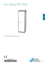
Dürr Dental PTS 200

Installation and Operating Instructions

Summary of Contents for PTS 200

Page 1: ...EN 9000 619 14 30 2012 02 Dürr Dental PTS 200 Installation and Operating Instructions ...

Page 2: ......

Page 3: ...n module set up 14 9 2 Connect air suction and waste water hoses to the floor connec tions of the PTS 15 9 3 Connect suction unit 15 10 Install compressed air module 16 10 1 Install the compressor generator 16 10 2 Install drying unit 17 10 3 Install amalgam separator 18 10 4 Install and connect BUS adapter 19 11 PTS electrical connections 20 12 Start up 22 13 Connection media plan 24 13 1 Set up ...

Page 4: ...to the relevant version of the equip ment and the underlying safety standards val id at the time of going to press All circuits processes names software and appliances quoted are protected under industrial property rights This translation of the Installation and Operat ing Instructions has been carried out in all good faith Dürr Dental deny any liability for in accurate translation and in the case...

Page 5: ...duty to mention the following safety measures in order to pre vent any possible danger When using this appliance all local and rele vant regulations must be observed Converting or modifying the appliance in any way is strictly prohibited In such cases any and all guarantees immediately become invalid The operation of modified appliances can be punishable by law In the interests of trouble free ope...

Page 6: ...nce or other information Take environmental and ambient condi tions into account Do not operate the unit in damp or wet conditions Unplug at the mains and remove all power Further Warnings and Symbols concerning indi vidual devices can be found in the relevant In stallation and Operating Instructions supplied with that device 3 1 Model identification plate The model identification plate is positio...

Page 7: ...2 VS 600 S built in 7128 01 021 Cabinet upper section 0949 526 52 Membrane drying unit 1650 980 00 DUO compressor generator 5250 100 56 DUO compressor generator conver sion unit 0949 500 52 CA 4 Amalgam Separator for PTS 7805 200 50 PTS 200 11 Model 0949 200 11 Model type 400V 3 50Hz Cabinet base unit with VS 900 S 0949 511 52 V 900 S built in 7131 02 021 Cabinet upper section 0949 512 52 Membrane...

Page 8: ... 0949 200 22 Model type 230V 1 50Hz Cabinet base unit with VS 600 S 0949 522 52 VS 600 S built in 7128 01 021 Cabinet upper section 0949 523 52 Membrane drying unit 1650 980 00 DUO compressor generator 5250 100 56 CA 4 Amalgam Separator for PTS 7805 200 50 PTS 200 31 Model 0949 200 31 Model type 400V 3 50Hz Cabinet base unit with VS 900 S 0949 501 52 VS 900 S built in 7134 02 021 Cabinet upper sec...

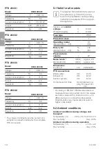
Page 9: ...urrent consumption A 19 2 Output kW 4 1 Weight ca kg 301 PTS 200 11 Model 0949 200 11 Voltage V 400 3 Frequency Hz 50 Current consumption A 7 3 10 4 Output kW 3 5 4 9 Weight ca kg 237 PTS 200 12 Model 0949 200 12 Voltage V 400 3 Frequency Hz 50 Current consumption A 10 4 Output kW 4 9 Weight ca kg 265 PTS 200 13 Model 0949 200 13 Voltage V 400 3 Frequency Hz 50 Current consumption A 10 6 Output kW...

Page 10: ...nd Operating Instructions supplied with the appropri ate appliance Suction unit control voltage PTS with display V V 24 AC 24 DC Fuse type IP20 Protection class 1 Operating model 0949 200 04 05 S1 S3 Duty cycle 0949 200 04 05 100 80 Pressure tank volume l 20 Noise levels Model 200 13 dB A dB A approx 53 approx 56 Dimensions H x W x D cm 205x64x61 PTS connections Waste water Exhaust air Suction sys...

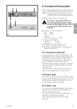
Page 11: ... monitors the pressure in the pressure tank The compressor generator is au tomatically switched on and off depending on the pressure settings which have been set up and the actual pressure within the tank Air at atmospheric pressure is drawn in through the suction filter and the inlet valve into the cyl inder chamber The piston in the cylinder compresses the air drawn in and supplies it to the dry...

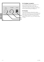
Page 12: ...ct the heavy metal particles and amalgam dust drawn into the system arising from fillings etc 6 5 Display This PTS model type is fitted with a display which gives information on the various operating states such as tank pressure 10 humidity 11 and amalgam separator 12 Additionally the display can be used to carry out various operati on steps 4 10 11 12 ...

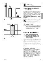
Page 13: ... 8 Set up and initial use Only fully qualified personnel are allowed to set up this appli ance to install it or to carry out commissioning For reasons of noise and the observance of the regulations concerning medical products it is strongly recommended to install the PTS in a side room Installation in a purpose built room e g in a boiler room must be checked with local building regulations Install...

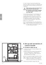
Page 14: ...onal ventilation must be provided The ideal ambient temperature range lies be tween 10 C and 25 C Approximately 70 of the electrical en ergy consumed by the compressor unit is converted into heat and then given up to the outside environment 9 Set up and connection of suction module 9 1 Suction module set up Unpack the suction module and place in the required location Ensure the suction module is a...

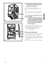
Page 15: ...g In the event that the used air cannot be extracted outside the premises then an exhaust air bacterial filter must be installed Feed the waste water hose compressed air hose and cable through the openings 22 or 23 and place temporarily in the PTS Cable Power cable 400V 230V control line 24V 9 3 Connect suction unit Connect the exhaust hose 24 od the suction unit to the floor connections of the PT...

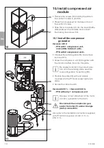
Page 16: ...ove from the PTS Screw the compressor unit 33 together with the vibration buffers 34 onto this plate Be careful to install in the correct posi tion onto the retaining plate see bore hole configuration for earthing 36 Position the plate 35 with unit already mounted into the PTS and screw tightly into place Secure the cable to earth Version 230 V 1 Version 230 V 3 PTS with only 1 compressor unit Obs...

Page 17: ...ing clamps 40 Place the second generator to mounting plate 35 of PTS and secure Place noise reducers 38 in position and fix 35 14 42 43 10 2 Install drying unit Choose the correct nozzle 43 Blue 1 compressor generator Magenta 2 compressor generators Insert the nozzle into the socket Place the filter and filter cover 42 in position ...

Page 18: ...gam separator The Amalgam Separator is only used in the PTS in combination with VS suction units The platform plate 46 is fixed using 4 screws 45 to the amalgam separator Place the waste water connection from the surge tank onto the inlet connection 48 of the amalgam separator and secure Slide the waste water hose 49 building wa ste water system onto the amalgam separa tor outlet point and secure ...

Page 19: ...Only for PTS with display Open the cover to the electronics of the amal gam separator Place 3 spacers 15 onto the BUS adapter 16 Connect the BUS adapter 16 to connection X9 of the amalgam separator electronic circuit board Feed the network line 17 through the amal gam separator housing and connect to one of the two BUS adapter network sockets Feed the Network line to the PTS control PCB and connec...

Page 20: ...tics according to EN 60898 This fuse must not be used for ad ditional devices as the max current consumption will then be exceeded Electric shock due to cable insula tion damage Electric shock Do not allow electrical cables to twist or bend Lay all electrical cables carefully and secure using cable ties Lay the prepared cable in the PTS fix in position and connect to the control PCB 50 refer to se...

Page 21: ...s to be fed from above into the control unit and then connected Drying units ventilation fan M5 and relief valve Y1 Depending on the model of PTS these are either connected to X1 with an adapter ca ble or directly connected to X21 and X23 Feed the cable through the conduit 53 se cure with cable tie and strain relief 52 Only for model PTS 200 03 230 V 3 Version Fault Do not connect Power Supply N ...

Page 22: ...trol PCB Operate the main switch a the compressor starts up and then switches off at c 7 5 bar Open the condensate tap 60 and drain off the condensation present Check the safety valve When carrying out this test the tank must be under pressure maximum 7 5 bar Open the screw 61 of the safety valve until the valve vents Allow the safety valve to vent only briefly and then close the screw again The v...

Page 23: ...e suction unit either by replacing a suction hose into the hose manifold or by switching the spittoon rinsing off VS Suction units run for approx 30 seconds after switching off Simultaneous signals to start from both the suction unit and the compressors cause the compressors to begin after a slight delay after the suction unit starts up Hang all panels 26 of the PTS 200 into place Danger of overhe...

Page 24: ...EN 24 2012 02 PTS 200 13 Connection media plan 13 1 Set up with VS units ...

Page 25: ...EN 2012 02 25 PTS 200 PC board 13 2 Set up with a display ...

Page 26: ...EN 26 2012 02 PTS 200 13 3 Set up with V units ...

Page 27: ...EN 2012 02 27 14 Circuit diagrams 14 1 Model type 400 V 3 PTS 200 PE X1 X4 2 3 X13 L1 L2 PE L3 N X7 X8 X11 X12 X5 PE U V W L N PE U1 V1 W1 PE U1 V1 W1 PE X21 X23 ...

Page 28: ...EN 28 2012 02 PTS 200 X10 X6 X4 X7 X21 X23 14 2 Model type 400 V 3 with display X11 X12 X13 X37 X31 X8 L1 L2 PE L3 N X27 ...

Page 29: ... 29 14 3 Model type 230 V 1 2 generators Circuit breakers Fusing LS switch 25 A with C or D characteristics according to EN 60898 PTS 200 PE 2 3 X4 X13 X7 X8 X11 X12 X21 X23 L N PE L N PE L N PE X5 L N PE L N PE ...

Page 30: ...EN 30 2012 02 14 4 Model type 230 V 1 PTS 200 PE 2 3 X4 X13 X7 X8 X11 L N PE L N PE L N PE X5 L N PE X1 X21 X23 ...

Page 31: ... 15 1 Model type 400V 3 parts 1 4 400 V 3 part 1 M5 Drying unit ventilation fan M4 Ventilation fan H1 Display module A1 Amalgam separator M3 Suction Unit M2 Compressor generator M1 Compressor generator X13 Power Supply 3 N PE AC 400 V ...

Page 32: ...EN 32 2012 02 400 V 3 part 2 Bleeder valve ...

Page 33: ...EN 2012 02 33 400 V 3 part 3 Display Top Optional Hose manifold con trol switch ...

Page 34: ...parator H1 Display module M1 Compressor generator M2 Compressor generator M3 Suction Unit M4 Ventilation fan M5 Drying unit ventilation fan Q4 Pressure switch S3 Main power switch X3 Display top X4 24 VAC Hose manifold contact X13 Power Supply 3 N PE AC 400 V ...

Page 35: ...1 X2 X6 3 M 1 M 3 M 3 M 1 M 8 40 8 X27 X4 X3 X32 X31 X8 X21 X11 X12 X6 X23 X10 X7 X13 F1 F2 X1 X30 PC board 0947 505 02 PC board 0947 505 03 X37 pressure humidity vacuum X1 X9 X20 X22 M5 M2 M1 Y1 H3 S3 M4 M3 3 N PE 400 V AC A1 A3 A4 A5 S0 A6 8 A1 Amalgam separator CA 4 with BUS adapter A3 Main PCB with performance functions A4 Control PCB A5 Display A6 PC Network M1 2 Compressor generator M3 Sucti...

Page 36: ...230 V 1 2 aggregates parts 1 4 230 V 1 part 1 A1 Amalgam separator H1 Display module M1 Compressor generator M2 Compressor generator M3 Suction Unit M4 Ventilation fan M5 Drying unit ventilation fan X13 Power Supply 1 N PE AC 230 V ...

Page 37: ...EN 2012 02 37 Model type 230V 1 2 aggregates part 2 Bleeder valve Drying unit ventila tion fan Pressure switch ...

Page 38: ...EN 38 2012 02 Model type 230V 1 2 aggregates part 3 24 VAC Hose manifold con trol contact ...

Page 39: ...0947 200 XX A1 Amalgam separator H1 Display module M1 Compressor generator M2 Compressor generator M3 Suction Unit M4 Ventilation fan M5 Drying unit ventilation fan Q4 Pressure switch S3 Main power switch X4 24 VAC Hose manifold contact X13 Power Supply 1 N PE AC 230 V ...

Page 40: ...L X21 M 1 M5 F4 F5 N L3 L1 3 L1 1 L1 Steuerung_L KOMPR_L1 L1 2 AGGR_EIN_VERZ 1 2 3 4 5 6 K1M 1 2 3 4 5 6 K3M 1 2 3 4 5 6 K2M 13 14 13 14 13 14 21 22 I I I 2 5 4A 1 3 5 2 4 6 Q1 13 14 21 22 I I I 2 5 4A 1 3 5 2 4 6 Q2 P Druck schalter 1 3 5 2 4 6 Q4 L1 X13 N L1 X11 N L1 X12 N L1 X7 N M 1 2 Z 2 U 1 U E P M4 M 1 M1 M 1 M3 N R17 N 1 N PE AC 230V 50Hz 15 4 Model type 230V 1 1 aggregat parts 1 4 230 V 1...

Page 41: ...4A F3 2a X6 2a 2 1a 1 S3 12 11 14 K7 Steuerung_L L1 2 AGGR_EIN_VERZ L1 1 KOMPR_L1 L1 2 1 1 1 14 2 2 1 2 24 12 14 11 K5 22 24 21 K5 A1 A2 K5 1 2 3 4 5 6 A1 A2 Q4 12 14 11 K12 22 24 21 K12 12 14 11 K6 4kW A1 A2 K1M 1 4kW A1 A2 K3M 1 4kW A1 A2 K2M 1 21 22 Q2 1 13 14 Q2 1 13 14 Q3 1 21 22 Q3 1 2 6 2 6 2 7 2 7 1 2 3 4 5 6 13 14 1 2 3 4 5 6 13 14 1 2 3 4 5 6 13 14 N N R17 230 V 1 1 aggregat part 2 ...

Page 42: ...5 4 3 1 3 X16 1 6 X25 5 4 3 1 3 X24 1 6 X15 5 3 2 1 3 X14 1 A1 A2 K9 12 14 11 K3 12 11 14 22 21 24 12 11 14 22 24 21 K4 12 14 11 K4 A1 A2 K4 A1 A2 K3 11 12 14 11 12 14 21 22 24 NO COM NC AC L AC N GND ZEIT START 1 2 3 4 6 4 6 X2 X1 K11 A1 A2 K10 12 14 11 K10 C15 ZEIT FKT GND AC N AC L NC COM NO 1 2 4 5 6 4 6 X1 X2 K1 NO COM NC AC L AC N GND ZEIT START 1 2 3 4 6 4 6 X2 X1 K2 2 1 1 1 14 2 2 1 2 24 A...

Page 43: ...X11 L1 X13 PE PE L1 X8 N PE L1 X9 N L1 X10 N X20 2 2a 1a 1 X6 2a 2 1a 1 S3 H3 N L N L PE X23 PE X21 N N N L1 L1 N N L1 X7 N M 1 M3 M 1 M1 1 N PE AC 230V PCB 0947 505 51 A1 Amalgam separator H1 Display module Q4 Pressure switch M1 Compressor generator M3 Suction Unit M4 Ventilation fan M5 Drying unit ventilation fan S3 Main power switch X4 24 V AC Hose manifold contact X13 Power Supply 3 N PE AC 23...

Page 44: ... Main power switch On I Off 0 Even when the power switch is in the off 0 position certain compo nents are still subject to live current e g pressure switch PCB of con trol unit b Relative humidity display Blue 30 Light red 30 c Pressure level display Start up 5 5 bar Switch off 7 5 bar d Amalgam Separator display panel e Display for operating state messages and operation of the PTS 27 a b c d e ...

Page 45: ... Change bacterial filter in the suction unit where present Every year Change filters in the compressor unit 71 and the dry air unit 72 and 73 Before changing the filter let off any pressure from the pressure tank To change the sinter filter 73 release the drying unit by undoing the 2 butterfly nuts 44 and re move from its mounting see section on mount ing dry air unit Undo the condensate collector...

Page 46: ... as follows Switch off PTS at mains switch a Set switch S2 75 to 1 Switch on PTS at mains switch a Red LED 76 lights Press switch 62 again on PTS will now run on one compressor Further information can be found in the Installation and Operating Instructions supplied with each appliance 18 2 PTS with display For PTS models with display follow instructions as necessary 30 75 a 62 S2 76 ...

Page 47: ......

Page 48: ...Dürr Dental AG Höpfigheimer Strasse 17 74321 Bietigheim Bissingen Germany Fon 49 7142 705 0 www duerr de info duerr de ...

Reviews: