1036100102L02 1904V002
19
Assembly
8 Installation
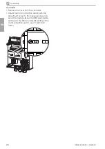
8.1 Remove the transport locks
The unit is securely protected with two foam
blocks and a retaining strap for safe transport.
i
Cut and remove the retaining strap.
i
Remove the foam blocks.
i
Check the unit for damage in transit.
8.2 Establishing the compressed
air connection
The devices are designed as standard for
a nominal pressure of 7 bar. Exceeding
the nominal pressure on a regular basis
will reduce the service life of the device.
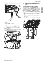
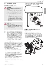
The unit is equipped as standard with a control
gear, which consists of a pressure switch, pres-
sure gauge, safety valve, non-return valve and
condensate drain.
In order to avoid the transfer of vibrations, we
recommend installing a flexible pressure hose
between the pressure hose and the pressure
switch. A pressure reducer can also be con-
nected.
i
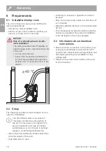
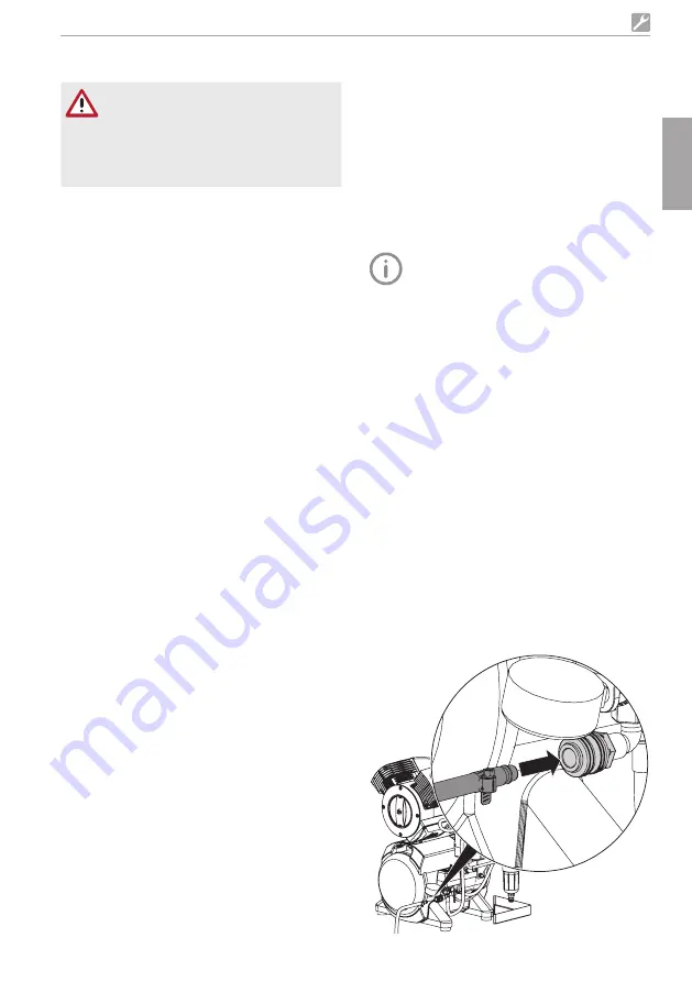
The compressed-air supply is connected to
the quick-release coupling (incl. hose adapter
piece) or to the pressure switch by means of a
G 1/4" internal thread.
i
Secure the pressure hose to the hose adapter
piece using a hose clip.
i
Connect the hose adapter piece to the
quick-release coupling.
7 Transport
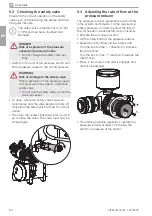
WARNING
Risk of explosion of the pressure
tank and pressure hoses
i
The pressure tank and the pressure
hoses must be vented before they are
stored or transported.
i
Protect the unit against moisture, dirt and ex-
treme temperatures during transport ("4 Tech-
nical data").
i
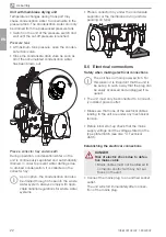
Always make sure that the condensate collec-
tor chamber is empty before transporting the
unit ("8.5 Draining the condensation water").
i
Always transport the unit in an upright posi-
tion.
i
Only transport the unit using the transport
handles provided.
i
Check the unit for transport damage.
EN
Summary of Contents for H2A-160M
Page 2: ......

