6.4
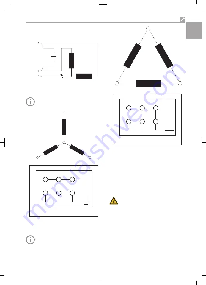
Circuit diagrams
Single-phase ac motors
CB
CB
.
N
.
.
L
Z1
U2
U1/Z2
U1/Z2
Fig. 6: Single-phase ac motors
Three-phase current / Y-connection
Images are shown schematically.
W1
W2
U2
U1
V1
V2
W2
U2
V2
U1
V1
W1
L1
L2
L3
PE
Fig. 7: Three-phase current / Y-connection
Three-phase current / delta connection
Images are shown schematically.
W1
V2
W2
U1
U2
V1
W2
U2
V2
U1
V1
W1
L1
L2
L3
PE
Fig. 8: Three-phase current / delta connection
6.5
Motor protection - tempera-
ture
3-phase motors
The electric motor can overheat!
The electrical connection must be performed in
accordance with the circuit diagram "6.4 Circuit
diagrams".
Units with a temperature switch start
again automatically after they have cooled
down.
Assembly
1035200220L02 1911V002
21
EN

