BIO-FIGHTER® ULTRA-FLEX INSTALLATION & OPERATION MANUAL
3
UV-C Light Hazard.
UV-C light can cause temporary or perma-
nent loss of vision, and sunburn. To prevent
exposure, do not install device in any appli-
cations that allows UV-C light to be visible
after installation.
WARNING
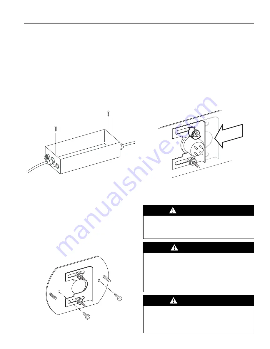
Fig. 1
Use included mounting screws to install device at desired
location.
Important:
The device must be installed in compliance
with all national and local electrical and
mechanical codes. Failure to do so will void
Dust Free® warranty.
MOUNTING THE BASE
(Fig.1)
Remove the cover and place the base at the
desired location. Use the included mounting
screws to install the base to the surface.
Replace the cover after the base is mounted.
FUSE
REMOTE LAMP BASE MOUNTING
(Fig.2)
Remove the remote lamp housing from the
remote lamp base by removing the knurled
nuts. Then install the remote lamp base to the
surface with the included mounting screws.
Using the remote lamp base as a template,
drill a 1" hole for the lamp.
Fig. 2
Lamp is secured with a sliding bracket tightened with two
knurled nuts.
INSTALLING THE LAMP
(Fig.3 )
To maximize the efficiency and life of the UVC
lamp, clean each lamp prior to installation.
Use isopropyl alcohol and cotton cloth to wipe
dust and fingerprints from the lamp.
Gently insert the lamp into the lamp hole.
Slide the bracket over the retaining lip of the
lamp and tighten the two knurled nuts until the
lamp is securely fastened. The lamp seals
against the base of the unit using a rubber
grommet which prevents air leaks. Repeat for
each lamp of the installation.
Fig. 3
Lamp is secured with a sliding bracket tightened with two
knurled nuts.
Clean lamp(s) prior to installation.
Failure to remove dirt and fingerprints from
the lamp(s) could shorten their lifespan.
NOTICE
Sharp Edge Hazard.
Be careful of sharp edges on device and
HVAC equipment while installing the device.
Personal injury may result.
CAUTION


