
DUST FREE
®
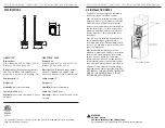
LIGHSTICK™/ LIGHTSTICK™ PLUS INSTALLATION & OPERATION MANUAL
DUST FREE
®
LIGHSTICK™/ LIGHTSTICK™ PLUS INSTALLATION & OPERATION MANUAL
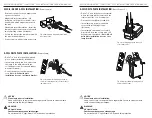
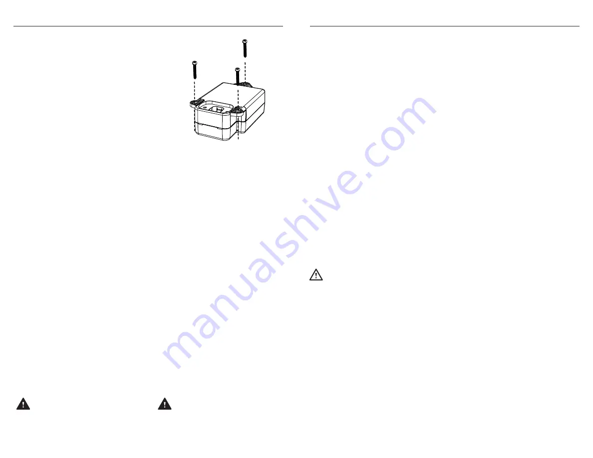
• With the lamp cordage facing away
from the mounting surface, use the long
mounting screws and install the power
module in a suitable location inside the
control panel of the air handler using
two self-drilling screws (included).
NOTE: DO NOT OVERTIGHTEN
SCREWS.
• Connect the power module to constant
24V power.
• Connect input 24V power cord. Align
markers on power module with power
cord connector.
• Connect lamp connector to power
module connector. Connectors are
keyed for proper alignment.
Be sure to
fully seat the connectors for proper
electrical connection and water
resistance.
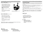
• With the lamp directly connected to
the power module, connect the power
module to the mounting surface using
the short, self drilling screws (included).
• Connect the power module to constant
24V power.
• Connect input 24V power cord. Align
markers on power module with power
cord connector.
INSTALL POWER MODULE
(Remote Lamp)
CONNECT LAMP
INSTALL POWER MODULE
(Direct Connect™)
The device must be installed in compliance with all national and local electrical and
mechanical codes. Failure to do so will void warranty.
WARNING
For Use with 24V Only..
Do not exceed voltage rating.
Severe damage to device and/or fire
could result. Verify proper voltage.
WARNING
Electric Shock Hazard.
Can cause injury or death.
Disconnect all electrical power
supplies before servicing.
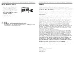
24V INSTALLATION NOTES
Installing the 24V UV fixture may require an upgrade to the 24V transformer in the furnace,
or air handler, depending upon the capacity of the OE specified by the manufacturer of the
AHU / furnace.
1. Verify the available volt amps prior to connecting the UV fixture to the 24V circuit.
Energize all 24V components so they reach their maximum amp load (Straight cool system
- activate cooling. Heat pump - activate heating mode.)
2. After obtaining the available volt amps, determine if the existing transformer can
accommodate a 1.4 amp load:
3. After installing the UV fixture, energize all 24V components at their full amp draw,
including the UV fixture, and ensure that all systems are operational and that fuses remain
intact.
4. RECOMMEND CONNECTING TO A DEDICATED 40VA CLASS 2 TRANSFORMER IF
EXISTING TRANSFORMER CANNOT ACCOMMODATE AMP LOAD RECOMMENDED
ABOVE.
NOTICE
Fully Seat Lamp Connector.
Failure to properly seat lamp connec-
tor could result in improper lamp
operation and/or compromise water
resistance.
Fig. 5A Flip power module over and secure with
long screws. Do not overtighten.


