background image

FREQUENCY CONTROL 

PANELS

INSTALLATION, MAINTENANCE and OPERATION GUIDE

3

On The Control Panel The Speclal Securlty Equlpment 

And Recommendations


May result in electrical shock or death.

In the wrong intervention to the control panel 
may cause damage to the panel.


Control panel electronic card in order to protect from 

extemal factors is made of plexiglass with a specially 
designed insulation protection is available. 


This protection panels and electronic card intervene 
must not removed by unauthorized persons.

Efficient Use of Energy Saving Information


Pumps and motors energy-consuming products. 
Personal causes and is extremely important for the 
national economy.


Control panel suitable motor and pumps be used.


All electrical connections to the instructions by 
providing appropriate and accurate; Be provided to 
prevent any loss and leakage of electricity.

Usage Life

The product is determined by the Ministry of Industry 
and declared usage life (time required to carry out the 
functions of the appliance spare parts) 10 years.

1. TRANSPORT / STORAGE / MONTAGE 

1.1 Transfer


Handle carefully control panels.


Appropriate size of the control panels are shipped in 

cardboard boxes.


Do not remove the cardboard box inside the control 

panels during transport.

1.2 Transport


Measure damage to the panel, and bad weather 

conditions during transport should be taken to avoid 

exposure.


Received by the panel in order to comply with the 

model and should be checked for any damage during 

transport.


If the clipboard contains a damaged or missing 

damage assessment report should be given written 

information to the shipping company our company.

1.3 Storage


Control panels of instead of immediately montage if not ;


Do not store in damp environments.


Do not put weight on the control panels.


Protect from direct sunlight at the control panels. 


Keep out of the control panels watertight.

1.4 Montage 


When performing mounting, follow the 

Instructions otherwise It may be damaged 
panels.


Montage are not observed instructions 

during the that as a result of electric shock, 
serious injury or death may result.


While mounting nuts at the rear of the control panel 
should be mounted with suitable screws.


Do not mount the back of the board is drilled 
with another screw. This may cause damage to the 
electronic card.


Control panel electrical connection must be carried 
out only by qualified personnel necessary safety 
precautions.

2. OPERATING


Control panel electrical connections should be 
checked.


The control panel should be checked that the cover is 
closed. 


There is power cut, the phases should be checked to 
be complete.


Control panel settings to be used should be based 
on pump or motor. Introduction to the settings 
menu, you will find that you are using the appropriate 
settings to the clipboard

3. MAINTENANCE 

 3.1 Monthly Maintenance


Disconnect electrical power before  

maintenance operations.


Control panel electrical connections should be 

checked relaxation.


The grounding line of the control 

panel should be checked. 


Electric cables, abrasion, puncture should be 

examined for color change and warming.

Summary of Contents for FGE-01

Page 1: ...INSTALLATION MAINTENANCE and OPERATION GUIDE FREQUENCY CONTROL PANELS...

Page 2: ...www duyarpompa com Control panels to get the best results this manual information must read carefully This manual all your problems can help solve...

Page 3: ...SERIES PANEL GENERAL INFORMATION 4 4 1 General Specifications of the Product 4 4 2 Technical Specifications of the Product 4 5 FGE SERIES PANEL TECHNICAL TABLES AND VISUALS 5 6 FLK SERIES PANEL GENER...

Page 4: ...ble damaged and torn Do not place heavy objects on the power cord and do not make an operation on the cable or injure Cables may be damaged and may cause a fire or electric shock In such cases please...

Page 5: ...ld be checked for any damage during transport If the clipboard contains a damaged or missing damage assessment report should be given written information to the shipping company our company 1 3 Storag...

Page 6: ...rotate at desired speed in every condition panels with frequency inverters that generate various frequencies and make the motor work at a stable speed are produced These panels work by adjusting the...

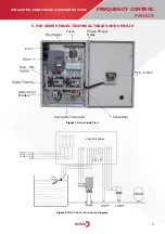
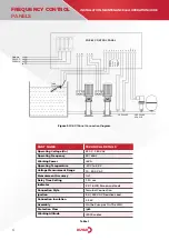
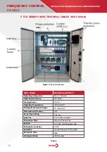
Page 7: ...V U TANK FLOATER 3 4 5 2 1 CONTROL PANEL U V W X Y Z PRESSURE SWITCH L1 L2 L3 Network 380V AC 50 60Hz N 8 9 DC 7 6 MANUEL REMOTE START AUTO REMOTE START B1 PRESSURE SENSOR PLC Control Breaker Thermost...

Page 8: ...Voltage Un Operating Frequency Working Power Operating Temperature Voltage Measurement Range Measurement Accuracy Delay Time Setting Indicator Connection Style Ignition Connection Insulation Assembly...

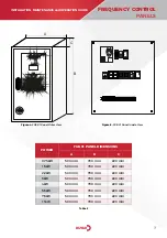
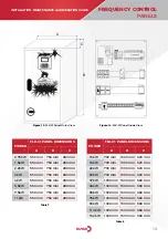
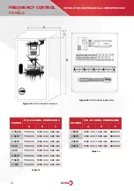
Page 9: ...TTENTION MUST BE CONNECTED TO THE GROUNDS FGE Ser es Control Un t GE R N E C M Y E Figure 4 FGE 01 Panel Outer View Figure 5 FGE 01 Panel Inside View POWER FGE 01 PANEL DIMENSIONS A B C 0 75kW 1 5kW 2...

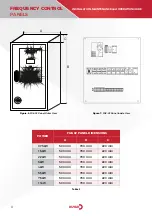
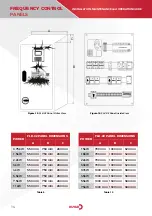
Page 10: ...NDS FGE Ser es Control Un t GE R N E C M Y E F1 T1 SRC P1 P2 1F1 2F1 R1 1K1 1K2 2K1 2K2 Q Figure 6 FGE 02 Panel Outer View Figure 7 FGE 02 Panel Inside View POWER FGE 02 PANEL DIMENSIONS A B C 0 75kW...

Page 11: ...Ser es Control Un t GE R N E C M Y E F1 T1 SRC P1 P2 P3 1F1 2F1 3F1 R1 1K1 1K2 2K1 2K2 3K1 3K2 Q Figure 8 FGE 03 Panel Outer View Figure 9 FGE 03 Panel Inside View POWER FGE 03 PANEL DIMENSIONS A B C...

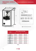
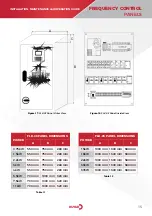
Page 12: ...rol Un t GE R N E C M Y E F1 T1 SRC P1 P2 P3 1F1 2F1 3F1 R1 4F1 P4 1K1 1K2 2K1 2K2 3K1 3K2 Q 4K1 4K2 Figure 10 FGE 04 Panel Outer View Figure 11 FGE 04 Panel Inside View POWER FGE 04 PANEL DIMENSIONS...

Page 13: ...ay output Real time dating Soft work Engagement with each pump driver Remote set switching feature Remote on off digital input Auto Test Settings Reel Time Clock Ability to set 2 different working tim...

Page 14: ...age Un Operating Frequency Working Power Operating Temperature Voltage Measurement Range Measurement Accuracy Delay Time Setting Indicator Connection Style Ignition Connection Insulation Assembly Prot...

Page 15: ...L DIMENSIONS A B C 0 75kW 1 5kW 2 2kW 3kW 4kW 5 5kW 7 5kW 11kW 550 mm 550 mm 550 mm 550 mm 550 mm 550 mm 550 mm 550 mm 750 mm 750 mm 750 mm 750 mm 750 mm 750 mm 750 mm 750 mm 280 mm 280 mm 280 mm 280...

Page 16: ...02 Panel Outer View Figure 16 FLK 02 Panel Inside View POWER FLK 02 PANEL DIMENSIONS A B C 0 75kW 1 5kW 2 2kW 3kW 4kW 5 5kW 7 5kW 11kW 550 mm 550 mm 550 mm 550 mm 550 mm 550 mm 550 mm 550 mm 750 mm 7...

Page 17: ...3K2 R1 Q Table 11 Table 12 Figure 17 FLK 03 Panel Outer View Figure 18 FLK 03 Panel Inside View POWER FLK 03 PANEL DIMENSIONS A B C 0 75kW 1 5kW 2 2kW 3kW 4kW 5 5kW 7 5kW 11kW 550 mm 550 mm 550 mm 550...

Page 18: ...1 3K2 Q AUTO MANUEL 4K1 4K2 15 15 Table 13 Table 14 Figure 19 FLK 04 Panel Outer View Figure 20 FLK 04 Panel Inside View POWER FLK 04 PANEL DIMENSIONS A B C 0 75kW 1 5kW 2 2kW 3kW 4kW 5 5kW 7 5kW 11kW...

Page 19: ...adjust the frequency of the network If it were possible it would be possible to control the speed of the engine Frequency converter to control the speed of the motorIt is a method used for giving way...

Page 20: ...Inverter S D Inverter S D Inverter S D Inverter S D Inverter S D Inverter S D Inverter S D Inverter S D Inverter S D Inverter S D Inverter 380 220V AC 380 220V AC 380 220V AC 380 220V AC 380 220V AC...

Page 21: ...FREQUENCY CONTROL PANELS INSTALLATION MAINTENANCE and OPERATION GUIDE 19 10 CABLE SECTION SELECTION CHART Table 16 SECTION mm POWER kw CURRENT LOAD A...

Page 22: ...g vibration storage physical collisions damage and malfunction caused by chemical factors and environmental conditions 6 Fire lightning floods earthquakes and other natural disasters damage and malfun...

Page 23: ...2021 11 1 WE ARE SENSITIVE TO LIFE...

Reviews: