background image

SDI-W 

Feb ‘19 


- 8 -

Installation - Electrical 


General Information. 


For 3 Phase Units: 
Connect ground wire to Protective Earth terminal. 
Bring power to L1, L2, L3. 
See page 10 for start-up procedures. 
  
For 1-Phase Units: 
Connect ground wire to Protective Earth terminal. 
Bring power to L1 and L2. 
See page 10 for start-up procedures. 


It is your responsibility to ensure that the Compressor 
Unit is electrically connected in a safe and correct 
manner. 

Any electrical work should be carried out 

by a competent Electrician and be done in such a 
way that it meets all applicable Codes and 
Regulations.


Ensure that a suitable Fused Disconnect or Breaker (by 
others than DV Systems) is installed in the electrical 
supply before the Compressor Unit. 
 
A Magnetic Starter is an integral part of the 
Compressor Unit circuit as it provides overload 
protection to the electric Motor. (The ‘IS5-4060-03’ 
Units have Motors equipped with an internal Overload, 
and a Starter is therefore not provided or required.) 


Failure to correctly connect the 
Compressor to your building's electrical 
services may result in serious personal 
injury or damage to the equipment. 


Before servicing the Unit, ensure the power 
source has been shut down and locked off. 


Read and understand the information 
contained in this manual before installing 
or operating the Unit.  


This product must be connected to a 
grounded, metallic, permanent wiring 
system, or an equipment-grounding 
terminal or lead on the product. 


Failure to observe any of the above 
precautions could result in severe personal 
injury or death, and/or damage to the Unit. 

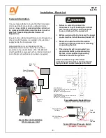
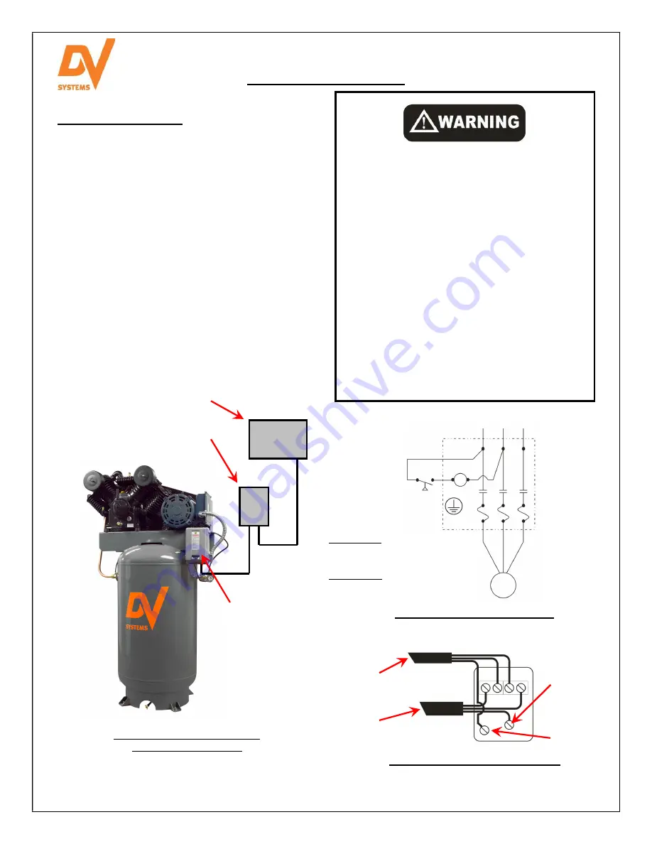
Main Fuse 
Box 

Fused Disconnect 
or Circuit Breaker 

Magnetic 
Starter 

Typical Electrical Installation 

Of a Compressor Unit 

L1      L2      L3 

Pressure 

Switch 

Motor 

Typical Magnetic Starter Wiring 

(Subject to Local Codes and Authorities) 

Typical Wiring at Pressure Switch 

(‘IS5-4060-03’ Units Only) 

Field 
Ground 

Motor 
Ground 

Factory Wiring 

To Motor 


220 Volt Power 

(#12 Wire) 

Coil 

Protective 

Earth 

Summary of Contents for IS10-100120

Page 1: ...ead this manual before installing or using your Air Compressor Unit It contains valuable information that will help in the receiving installation use and maintenance of the Unit Please keep this manual in a safe place for future reference All of the information policies and procedures in this reference manual apply exclusively to DV Systems DV Systems Inc 490 Welham Road Barrie ON L4N 8Z4 Tele 705...

Page 2: ... starts and stops automatically do not come into contact with moving parts Shut off all power to the Unit before attempting any repair or maintenance work Air compressed by the Unit is not suitable for inhaling It may contain vapours harmful to your health Compressor capable of pressures 50 psi Never directly inhale compressed air produced by the Compressor Risk of injury do not direct air stream ...

Page 3: ...il mineral 2 Check condition alignment of Belts Pulley 3 Check Safety Valves Check that Unit unloads when shutting down Clean and or blow dust dirt off Unit Inspect Check Valve Inspect Pressure Gauge Notes 1 Air Filters are available separately or in the Maintenance Kit Consult the Pump breakdown 2 Mineral Oil is available separately or in the Maintenance Kit Consult the Pump breakdown 3 Belts and...

Page 4: ...e damage be noticed only after the product has been received contact the transport company immediately to file a claim Depending on the problem it may be wise to photograph the damage Also it may be wise to discuss with the carrier representative the time allotted to give notice of loss or damage to the product there may be guidelines which limit timeframes of same 4 Do not attempt further unpacki...

Page 5: ... Tube Allows the compressed air to cool as it transfers from the Pump to the Tank Electric Motor Check Valve Installed between the Aftercooler and the Tank and allows the compressed air to enter the Tank but prevents it from flowing back out Air Receiver Tank Stores the compressed air Magnetic Starter An electrical device which receives a signal from the Pressure Switch and allows power to flow to...

Page 6: ... ensure that the structure can safely support the weight of the Unit The Vibration Pads will help to lessen the sound level of the Unit caused by harmonics created by the structure All Compressor Units must be anchored and installed as shown below Failure to do this will affect the Tank Warranty Ensure that the floor under the Unit is smooth level and capable of bearing the weight of the Compresso...

Page 7: ... Crankcase Add oil as required Serious damage may result from use however limited without oil Use of improper oil may negatively affect Compressor performance or shorten Unit life Resulting problems are not covered by the DV Systems Warranty Condensation water may form in the Pump if the Compressor has limited use or is installed in a very humid environment As the water will tend to settle on the ...

Page 8: ...ts have Motors equipped with an internal Overload and a Starter is therefore not provided or required Failure to correctly connect the Compressor to your building s electrical services may result in serious personal injury or damage to the equipment Before servicing the Unit ensure the power source has been shut down and locked off Read and understand the information contained in this manual befor...

Page 9: ...ystems Unit works as designed and required you must ensure that it is correctly wired to your building service It is the responsibility of your Licensed Electrician to ensure that The Unit you purchased is suitable for your particular buildings electrical service Protective devices such as Magnetic Starters Fused Disconnects etc have been sized and installed correctly Any electrical accessories pu...

Page 10: ...actory pre set maximum pressure and the head pressure is released at the Pressure Switch 7 Measure the amp draw as the Unit reaches maximum pressure 8 Once off check the Compressor and piping systems for any air leaks Correct as required Shut off all power to the Compressor Unit before attempting any repair or maintenance During the first few days of operation check the Unit periodically to ensure...

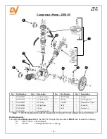
Page 11: ...411 Tank Ball Valve VA 9705 VA 9705 VA 9705 VA 9705 Check Valve CCV 9401 CCV 9406 CCV 9406 CCV 9406 Note A The Filter Assembly and internal Filter Element were changed in 2012 The older style Element is still available and the Filter Elements are not interchangeable Please measure the Element to determine which Filter Assembly Filter Element and Maintenance Kit is correct for your Pump Older Assem...

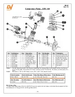
Page 12: ...ilter Assembly and internal Filter Element were changed in 2012 The older style Element is still available and the Filter Elements are not interchangeable Please measure the Element to determine which Filter Assembly Filter Element and Maintenance Kit is correct for your Pump Older Assembly Older Filter Element Older Filter Element Dimensions Older Maintenance Kit PB 21176001 PB 21177013 4 1 8 OD ...

Page 13: ...Oil Seal GK 40 1 Gasket Kit 5 PB 21212003 1 Flywheel OK 40 1 Overhaul Kit Note 1 The VRK 40 Valve Repair Kit includes the Valve Plates and the Gaskets necessary to install them 2 The previous DEV 40 Pump did not have the Fan Assembly and Shroud Assembly All other components remain the same 3 OK 40 Overhaul Kit includes 1 Gasket Kit 1 Ring Kit 3 Valve Repair Kits and 1 Oil Seal Maintenance Kits The...

Page 14: ... 8 TIA 5075 1 Safety Valve 75 psi 3 PB 21164004 1 Oil Sight Glass GK 55 1 Gasket Kit 4 PB 21161005 1 Oil Seal OK 55 1 Overhaul Kit 5 PB 21166001 1 Crankcase Breather Note 1 OK 55 Overhaul Kit includes 1 Gasket Kit 1 Ring Kit 1 Valve Repair Kit and 1 Oil Seal Maintenance Kits The appropriate Maintenance Kit for the DEV 55 Pump is the part number MK 55 and includes the following 2 PB 21177010 Filter...

Page 15: ...e Filter Assembly and internal Filter Element have changed The older style Element is still available and the Filter Elements are not interchangeable Please measure the Element to determine which Filter Assembly Filter Element and Maintenance Kit is correct Note B Please order 1 PB 11122004 Washer for every PB 21124011 Valve Assembly ordered Older Assembly Older Filter Element Older Filter Element...

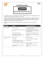
Page 16: ...er to the Unit Loose and or missing wires in the electrical circuit Starter Overload is tripped Pressure may not be low enough in the Tank to allow the Unit to start Check that power at the disconnect or breaker is on Also check any fuses Check that all wiring connections are tight With a wiring schematic check that all wiring is present and correct Reset the overload in the Magnetic Starter Drop ...

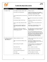
Page 17: ...ntake piping from building Worn Main Bearings can usually be detected by noticeable end play on the Flywheel Replace the Main Bearings Worn Connecting Rod Bearing Inserts can be detected by removing a Valve and watching the Piston while moving the Flywheel by hand If the Flywheel can be moved at mid stroke without the Piston moving the Bearing Inserts or Connecting Rod may need to be replaced D Oi...

Page 18: ...er Head Aftercooler Tube or Check Valve Maximum operating time based on an 8 hour day is 60 which related to approx 35 minutes per hour Clean Pump Move Compressor so Beltguard is a minimum of 18 away from nearest obstruction See Page 7 Correct rotation of the Flywheel See Page 10 Fix leaks Soap water mixture will assist in finding small leaks Clean or replace piping Replace Air Filter Refer to Lub...

Page 19: ...Screws Cylinder Head Cylinder or Crankcase Oil Seal leak Use care when filling with oil Wipe any spills immediately Drain oil until proper level is reached Check Filler Plug Change O Ring Ensure Pipe Nipple and Cap are sealed Initially retorque fasteners to factory specs If leaks persist replace Gasket Use Loctite Form a Gasket on Head Bolts and Crankcase to Cylinder Bolts Inspect Crankshaft for a...

Page 20: ...that may generally have a known useful life including but not limited to compressor pump rings valves and bearings The Manufacturer shall determine in its sole and reasonable discretion if a Product or part of a Product has been subject to Ordinary Wear and Tear This Warranty does not apply to Ordinary Wear and Tear In addition without limiting the foregoing this Warranty does not apply to all shi...

Reviews: