20
Istruction Manual ISI VOLUMETRIC/CHRONOMETER
6) BLACKOUT AND LONG PERIODS OF
INACTIVITY
In case of a blackout, the water softener is capable to keep
data for 6 hours
If the blackout lasts longer, it will be necessary to check the
settings.
In the event of a blackout during the regeneration cycle, the
water softener will save the step in which it was performing
before the interruption. When the blackout ends, the interrup-
ted step will be restarted and the regeneration will be com-
pleted.
7. MANUAL SETTINGS (Without Password)
7.1 POSTPONED REGENERATION (fig. 6, A)
Press briefly
, a flashing dot will appear on the display.
This means that the regeneration will be performed at the set
time(par.5.4), without modifying the program.
If you press the button once more, the flashing dot will disap-
pear and the command will be cancelled.
7.2 MANUAL REGENERATION (fig. 6, A)
To start a complete regeneration cycle immediately, press and
hold down
until the display shows two lines in vertical fall,
indicating that the regeneration is in progress.
The regeneration is made up of 7 steps, all associated to the
letter “C”:
C1 backwash
C2 salt injection and rinse
C3 re-pressurisation
C4 quick rinse
C5 second backwash
C6 second quick rinse
C7 loading of water in the brine
7.3 STEP SELECTION
To check the correct functioning of the different regeneration
steps, follow the instructions below:
1) Press and hold down until the display shows two lines
in vertical fall, a manual regeneration cycle will begin.
2) Wait for a few seconds, untill the display will show the
current step of the cycle, C1.
3) Press at the same time to pass to the following step
of the regeneration.
4) After few seconds the display will show (“C2”).
Repeating the previous commands, it is possible to past
all the 7 steps until the “service” position, and then the
display will show back the set time.
Press and hold
at the same time for 5 seconds,
water softener, whatever regeneration state it is, it will
position it self to the service step .
8) ADJUSTING THE MIXER SCREW
The water softener supplies hardness-free drinking water. In
some cases, however, it can be necessary to leave a residue
of hardness in the water.
The mixer allows a certain amount of water to pass directly
from the inlet to the outlet of the water softener, without being
softened by resins.
By loosening the mixer screw (fig. 9, E) you can gradually
increase the hardness of the outflowing water. Please remem-
ber that this operation must be carried out very carefully. At
the end of the operation, we suggest letting some water flow
out and measuring its hardness.
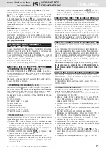
9) ANTI-OVERFLOW DEVICE (OPTIONAL)
If the water softener is equipped with an “Anti-Overflow” de-
vice (fig. 1).
It stops excess water from flowing into the brine tank due to
malfunctioning.
It detects excess water flowing into the brine tank, thanks
to a float that controls a mechanism that blocks water flow.
The brine level control system is a safety mechanism; con-
sequently, in case it triggers, we strongly suggest to check
its root cause.
Caution:
This device only works on the connection between the
valve and the brine tank; it does not replace the overflow
device that must always be installed as integral part of
our equipment (chap. 3.6).
10) MAINTENANCE FOR THE INSTALLER
During maintenance operations, all necessary precautions
must be adopted to preserve the hygienic integrity of the equi-
pment. Reparations and maintenance must be carried out
using original replacements.
10.1 PERIODIC MAINTENANCE
For an ideal working, it is advisable to perform the following
operations periodically:
1) Clean the brine and remove any sediment from the suction
pipe (fig. 1, B) every six months.
2) Clean the injector (fig. 9, B) and its filter (fig. 9, A) and the
brine control (fig.9, C) at least once a year, following the
instructions reported below:
• Close the water inlet and outlet taps (fig. 3, B, D)
• Press and hold
until the display shows two horizontal
lines.
• Wait for a few seconds, on display will appear C1.
• Unplug the fixture, unscrew and remove the injector (fig. 9,
B), the filter (fig. 9, A) and the brine control (fig. 9, C).
• Wash the components with water and make sure the hole
in the injector (fig. 9, B) isn’t blocked.
• Carefully place the parts again in their seats.
• Slowly open the water inlet and outlet taps, and wait for a
30 seconds.
• Plug the fixture.
• Press and hold
at the same time for 5 seconds.
The valve will automatically position to service step.
• The display will then show back the time (fig. 6, B and 7, B)
10.2 RESIN PRESERVATION AND ACTIVATION AFTER
A LONG PERIOD OF INACTIVITY
If the water softener is not to be used for more than 30 days,
it is necessary to do a manual regeneration (see par. 7.2).
We suggest avoiding a period of inactivity longer than 12
months. It is forbidden to reactivate the system after this pe-
riod of inactivity.
If the period of inactivity is shorter than 12 months, it is ne-
cessary to perform a resin rinse (see paragraph 7.2 “MANUAL
REGENERATION”) before reactivating the equipment.
10.3 DISCONNECTING THE EQUIPMENT
1. Close the inlet and outlet water taps (fig. 3, B, D)
2. Press and hold the
button for 5 seconds to start a quick
cycle of manual regeneration.
3. Wait a few seconds and check that the display shows the
C1 phase.
4. Wait 15 seconds, then unplug from the socket.
The equipment has now been depressurized and can be di-
ENGLISH
instruction manual
VOLUMETRIC
water softener
ISI
CHRONOMETER


