18
L28
FB60R/0603
DEN-3V3
.
R117
100K
.
C19
100NF
Q10
SI2323DS
1
3
2
Q11
2N3904
1
2
3
.
CP4
100NF
.
RP7
100K
Q8
SI2323DS
1
3
2
.
R114
100K
.
RP4
51K/1%
.
C26
100NF
.
C27
100NF
.
RP6
62K/1%
.
CP5
0.47UF
.
R119
10K
.
C20
1UF
.
CP2
10UF/10V
.
R116
10K
.
CP1
2.2UF/10V
DDR POWER
VDDCORE=1.15V
.
L3
10UH
+
EC1
220UF/16V
1
2
.
C18
1UF
Ferrite
.
FB26
BLM21PG331SN1D
.
R113
2K
Ferrite
.
FB25
BLM21PG331SN1D
.
C25
100NF
.
R115
10K
Q9
2N3904
1
2
3
.
R118
10K
.
C21
100NF
5V
VDD33
P5V
P3V3
HDMI5V
STD5V
5V
STD3V3
VDD33
VDDCORE
P5V
Ferrite
.
FB28
BLM21PG601SN1D
.
CP7
100NF
.
RP9
1M/1%/NC
IO POWER
PGND
.
CP12
4.7UF/10V
.
RP21
68K/1%
.
RP19
1K
UP2
APS2408
EN
1
GN
D
2
LX
3
VIN
4
FB
5
.
CP13
22PF
.
L6
2.2UH
.
CP14
100NF
+
EC3
220UF/16V
1
2
.
RP22
2K
.
RP20
300K/1%
.
CP16
100NF
.
CP15
10UF/10V
PGND
PGND
P3V3
P5V
PGND
PGND
PGND
PGND
.
RP23
1.6M/1%
TP37
Test Pin
1
.
BC162
4.7UF
U16
LD1117
IN
3
AD
J/
GN
D
1
OUT
2
OUT
4
.
BC142
0.1UF
STD3V3
.
BC161
10UF
VDDO=1.80V
VDDO
U8
AP2972
BS
1
GN
D
2
FB
3
EN
4
IN
5
LX
6
TC19
100UF/10V/NC
GND
NC
5V
GND
12V
3.3V
GND
GND
GND
STANDBY _CONTROL
.
D1
1N4148
DEN-3V3
STANDBY _CONTROL
F_STANDBY
F_STANDBY
[5]
STANDBY POWER
.
R820
1K
CORE POWER
There is leatage current from
PMU 3V3 to STD3V3, this
leatage voltage maybe cause
SY8009 can not shut down at
standby, so need a series
diode to solve this issue.
5V_AMP
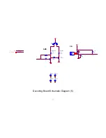
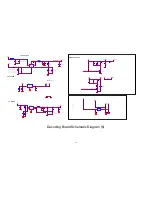
Decoding Board Schematic Diagram (6)
Summary of Contents for SMP012HDT2
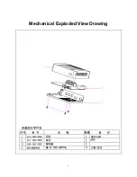
Page 6: ...6 Mechanical Exploded View Drawing ...
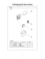
Page 8: ...8 Packaging and Accessories ...
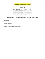
Page 10: ...10 ...
Page 11: ...11 ...
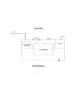
Page 12: ...12 Flowchart Wiring Diagram ...
Page 20: ...20 ...
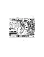
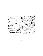
Page 22: ...22 Silkscreen of Decoding Board Top ...
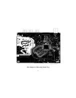
Page 23: ...23 Silkscreen of Decoding Board Bottom ...
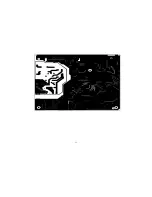
Page 24: ...24 PCB Diagram of Decoding Board Top ...
Page 25: ...25 PCB Diagram of Decoding Board Bottom ...
Page 33: ...33 25 26 27 28 29 30 31 32 33 34 35 36 37 38 39 40 41 42 ...


