background image

T

est Pattern

FPD shows Description

Fr

ame & 

Geometry

FGEO

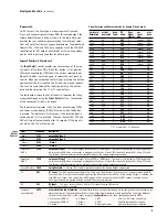
This test pattern con

tains two specific test features. The first is a 1-pixel wide box around the very outside of the image.

This is used to determine when the entire iScan output image is visible on the display. The arrows along the middle of
each edge provide an indication of the amount of overscan (if any). The blue boxes in the center of each quadrant are
used for measuring display geometry. The rectangle in the center of the gray boxes should appear square on a 4:3 aspect
ratio display, the next large rectangle should appear square on a 16:9 display, the next on a 1.85:1 display, and the largest
rectangle should be square on a 2.35:1 display. The blue boxes are also used as an indication that the horizontal position-
ing of the output image is correct. Due to the iScan HD

+

's 4:2:2 in

ternal processing, with a custom output resolution it is

possible to cause the Cb & Cr components to become reversed. If the blue boxes are displayed as red instead of blue, then
the Cb & Cr components are reversed. This can be corrected by ensuring that there is an even number of pixels in the sum
of the horizontal sync and horizontal back porch.

Brightness 
& Contrast

BRCN

This test pattern is composed o

f 4 quarter-screen blocks. Two of the blocks have a background level of standard black, 

and the other two blocks have a background level of standard white. Embedded in the black blocks are 3 bars. One is 4
IRE below black, one is 1 IRE above black, and the third is 2 IRE above black. Embedded in the white blocks are 3 bars.
One is 1 IRE above white, one is 1 IRE below white, and the third is 2 IRE below white. This test pattern is useful for 
setting display black and white levels. The bottom 2 blocks differ slightly from these levels. For the bottom 2 blocks, the
blacker-then-black bar is at the lowest possible luma level, and the whiter-than-white bar is at the highest possible luma
level. Also included in the pattern are 2 needle pulses, which can be used to check CRT voltage regulation as well as the
presence of scan velocity modulation.

1-Pixel 
Checkerboard

CHCK

This test pattern con

sists of a 1-pixel black and white checkerboard. The test pattern alternates black and white pixels in

both the vertical and the horizontal direction. This pattern is useful for exactly matching the iScan’s output resolution to
that of the display to achieve 1:1 pixel mapping and bypass any scaling operation which may be incorporated in the display.

1-Pixel
Vertical 
Lines

VLIN

This test pattern con

sists of an alternating series of 1-pixel black and white vertical lines. The test pattern alternates black

and white pixels in only the horizontal direction. This pattern is useful for exactly matching the iScan’s output resolution to
that of the display in order to achieve 1:1 pixel mapping and bypass any scaling operation which may be incorporated in
the display. Its use is similar to that of the 1-pixel checkerboard, but it operates only in the horizontal direction.

16

Input Select Buttons

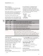
Th

ere are ten direct input selection buttons, as shown below.

P

ower Button

This button puts th

e unit into 

activ

e

or 

standb

y

m

ode. It has

the same functionality as the 

P

ower

button on th

e front panel.

Info

This activates th

e OSD to put up the Information box 

(described earlier).

Curtain

This button gr

adually puts up a black ‘curtain’ over the image. 

It may help prevent burn-in in plasma TVs or CRT based displays.
Pushing this button again removes the curtain.

T

est Patterns

This featur

e generates test patterns as an aid in matching 

the output of the iScan HD

+

to your display

. The test patterns

replace the normal output of the iScan and are rendered at the
iScan’s output resolution. There are 27 test patterns currently
available. The test patterns are activated via the 

T

est Patterns

button on th

e remote control. Pushing the button activates 

the currently selected test pattern. Pushing it again turns the
currently selected test pattern off, and reverts the unit to 
normal operation. 

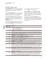
To select a test pattern to send to your display, use the

Configur

ation

button on th

e remote control or on the front

panel of your iScan HD

+

. Th

e first entry under the menu that is

displayed on the OSD is 

T

est Patterns

. Fr

om this menu, you can

select one of the 27 test patterns that you wish to display. After
you activate the desired test pattern using the 

T

est Pattern

but

-

ton on the remote control, you can change the currently selected
test pattern without returning to the 

Configur

ation

m

enu. You

can do this by using the “1” and “3” keys on the numeric keypad
of the remote control. The “1” key will move you backward in the
test pattern list, and the “3” key will move you forward in the
list. See the Test Pattern listing below for descriptions of each.

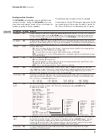
Remote Contr

ol Operation 

(continued)

VID1

Vi

deo 1 (Composite)

VID2

Vi

deo 2 (Composite)

S-VID1

S-Vi

deo 1

S-VID2

S-Vi

deo 2

COMP1

Compon

ent 1/RGB 1

COMP2

Compon

ent 2/RGB 2

P

ASSTHRU

An

alog Passthru

D

VI

DVI

A

UTO

A

utomatic active input detection and selection

SDI

SDI 

(SDI Video Input Module required)

T

est

Patterns

Menu

(T

est Patterns Menu table continues on the next page)

Summary of Contents for iScan HD+

Page 1: ...B Y A N C H O R B A Y T E C H N O L O G I E S 1 Product Guide English Version How to install set up and use your new DVDO product High Resolution Video Scaling Engine ...

Page 2: ...Standby Control 8 and Enter Exit Controls 8 Output Setup 8 Formats 9 Input Aspect Ratio Control 10 Picture Control 11 Saved Settings for Individual Inputs 11 Audio Operation 11 From the Front Panel From the On Screen Display OSD Digital Audio Outputs Input Adjust Control 12 Configuration Control 13 Customizing the Output Video Timing for your Display 14 Automation Controls 14 Remote Control Operat...

Page 3: ...es the key features and performance of the iScan HD This Product Guide will help you set up your new iScan HD and will also give you information on how to match it to your display as well as how to connect it to and use it with the rest of the components in your system Should you have any questions during the setup or operation of this DVDO product you should first contact your Authorized DVDO Res...

Page 4: ...put it is recommended that you connect the output to the iScan HD s DVI input The iScan HD will process both Standard and High Definition sources on it s DVI input including 480p 576p 720p and 1080i In addition the iScan HD will also process HDCP protected content on its DVI input However the iScan HD will only output HDCP protected con tent on its DVI output with HDCP enabled The iScan HD will no...

Page 5: ... Definition video source HD DBS Receiver PC or other High Definition video source AV Preamplifier Processor or AV Receiver Digital Audio Inputs Analog Audio Inputs or SDI Video Input Module required Signal Flow Diagram The following diagram shows a typical way to use the iScan HD in a system This figure depicts a system where the iScan HD is used as the primary video switcher or hub The iScan HD i...

Page 6: ...ial Digital Audio Cable Coaxial Component Video Source 480i 480p 720p or 1080i YPbPr VCR or Other S Video Source Component Video Source 480i 480p 720p or 1080i Set Top Box or Other DVI source HD Satellite TV Tuner PC or Progressive Scan DVD Player 5 x B N C 3 x R C A or or Video Game or Other Composite Video Source Set Top Box or Other S Video Source Video Game or Other Composite Video Source DVI ...

Page 7: ...m VGA to the BNC connectors used on the display These adapter cables are readily available through most home theater retailers and have a VGA connector on one end and BNC connectors on the other The BNC end of the cable will usually have five connectors labeled R G B Hsync and Vsync although not all will necessarily be needed for every display Please refer to your display s specifications to deter...

Page 8: ...ks 3 Change the sync type of the iScan HD from bi level sync to separate HSync and VSync There are four separate sync selections positive Hsync and Vsync H V positive Hsync negative Vsync H V negative Hsync positive Vsync H V and negative Hsync and Vsync H V Most formats default to negative Hsync and Vsync Refer to the Preset Format table on page 9 for more details 䊳 Push the Output Setup button u...

Page 9: ...eleases Sync Type SYNC Sets the synchronization signal type of the output format Press the or button first to show the current sync type Press the same button again to move to the next sync type Currently seven sync types are supported BI bi level sync on green luma in RGB colorspace sync is also present on red and blue signals TRI tri level sync on green luma in RGB colorspace sync is also presen...

Page 10: ... 1024 P PLA5 H V RGB 1024 852 P PLA6 H V RGB 1024 576 P DLP1 H V RGB 848 600 P DLP2 H V RGB 1365 1024 P DIL1 H V RGB 1400 1050 P DIL2 H V RGB 1400 788 P DIL3 H V RGB 960 540 P LCD1 H V RGB 1280 960 P QUA1 H V RGB 1440 960 P QUA2 H V RGB 1440 1152 P QUA3 H V RGB P progressive I interlace Preset Formats and Characteristics for Analog Video Output Input FPD shows Description Video 1 VID1 Composite Vi...

Page 11: ...ontrol Pushing the Enter Exit button shows the current Zoom setting Pushing and button increases or decreases the zooming factor VERT Vertical Zoom control Pushing the Enter Exit button shows the current Zoom setting Pushing and button increases or decreases the zooming factor Pan PAN The Pan function allows the image to be shifted up down left and right Note that the Pan function can only be used...

Page 12: ...ls Y C Delay YC D Adjusts the Y C differential Delay of the selected input signal Default is 0 Chroma Filter Auto CUE C CUEC Auto CUE C This feature removes chroma upsampling errors CUE found in some video sources which have been MPEG encoded and then improperly decoded There are three available settings OFF No chroma filtering Use this setting if the source does not have a CUE problem ON Chroma f...

Page 13: ... modes OFF BIAS and AUTO OFF Turns off film detection in the deinterlacer All video sources are treated as original video BIAS The Film Bias mode may improve film mode detection in some cases For example it may improve the detection of PAL SECAM film sources AUTO Source adaptive deinterlacing is on Auto Input Priority Selection AIPS The Auto Input Priority Selection function assigns different prio...

Page 14: ...al mode In Advanced user mode you have access to the complete set of output timing controls See the section entitled Customizing the Output Video Timing for your Display Push the button to see the current setting The FPD will display either NORM for normal or ADV for advanced user level Pushing the button again selects the alternate mode Serial Port Rate R232 The serial port is used by the automat...

Page 15: ... interface using the protocol specified in the Direct IR Controls document This document is also available from DVDO s website at www dvdo com faq faq_pro_man html 14 Output Timing Controls Description Horizontal Shift This setting shifts the image left or right in 1 pixel steps Increasing the setting shifts the image to the left while decreas ing the setting shifts the image to the right The widt...

Page 16: ...n the front panel See Input Adjust Control page 12 Use the navigation control buttons to select the desired function and adjust the settings Menu This button activates the top level OSD menu which lists the controls in the table below Use the navigation control buttons to select the desired function and adjust the settings Zoom This button puts the iScan HD into Zoom mode Unlike the Zoom function ...

Page 17: ...corporated in the display 1 Pixel Vertical Lines VLIN This test pattern consists of an alternating series of 1 pixel black and white vertical lines The test pattern alternates black and white pixels in only the horizontal direction This pattern is useful for exactly matching the iScan s output resolution to that of the display in order to achieve 1 1 pixel mapping and bypass any scaling operation ...

Page 18: ...attern is a coarse cross hatch useful for convergence and geometry on CRT displays It consists of a 75 white level hatch with approximately 20 divisions across the width of the image Fine Cross Hatch FINE This test pattern is a fine cross hatch useful for convergence and geometry on CRT displays It consists of a 75 white level hatch with approximately 40 divisions across the width of the image Foc...

Page 19: ...panel 䊳 Functions accessible via either On Screen Display OSD or front panel LED display 䊳 Fully programmable controls for each separate video input with non volatile memories Automatic input source detection and input priority selection Input aspect ratio select 4 3 fullframe 4 3 letterbox 16 9 fullframe or custom input aspect ratio Output aspect ratio select 4 3 5 4 16 9 or custom output aspect ...

Page 20: ...om wet locations such as bathtubs sinks laundries wet basements and swimming pools 䊳 Use only accessories recommended by the manufacturer to avoid fire shock or other hazards 䊳 Unplug your iScan HD before cleaning Use a damp cloth for cleaning Do not use cleaning fluids or aerosols which could enter the unit and cause damage fire or electrical shock These substances may also mar the finish of your...

Page 21: ...horized DVDO Reseller that the product will be free of electrical and mechanical defects that materially affect the product s operation as described in this Product Guide Anchor Bay Technologies sole obligation shall be at its sole option to repair or replace the product with equivalent or better or to refund the net original purchase price DISCLAIMER OF WARRANTY ALL IMPLIED WARRANTIES OF MERCHANT...

Page 22: ...chnologies Inc 300 Orchard City Drive M S 131 Campbell California 95008 email support dvdo com web www dvdo com toll free 866 423 DVDO fax 408 379 3845 iScan HD Product Guide April 2005 English Product Guide version 1 1 Firmware version 2 32 ABT P N 75 0238 02 ...

Reviews: