2-10
Pronto3 Hardware Guide
2.2.2 Digital Video I/Os
This section contains some further information about the digital video
in- and outputs of the Pronto3.
Generally DVS names the input/output channels (connectors/ports) of
the digital video signals alphabetically: the main video stream is then
available, for instance, on port A and the secondary video stream on
port B. However, because some systems offer more channels providing
sometimes different functions, the labeling of the ports can be supple-
mented by numbers. To simplify matters whenever feasible the main
video ports (ports A) may be labeled without an alphabetical or numer-
ic structuring.
For YUV you will usually use one channel (the main video ports, mostly
labeled ’A’, single link). For YUVA you will need two channels (’A’ for
YUV and ’B’ for the key signal). With RGB you will always need two
channels (’A’ and ’B’, dual link).
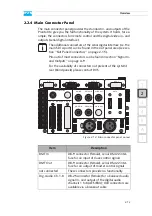
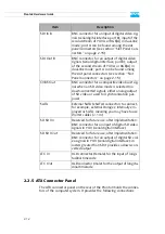
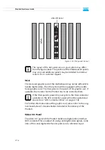
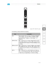
The Pronto3 provides two ports for an input as well as an output at the
rear of the system. Currently the SD-only ports provide no functionality
and are reserved for future use.
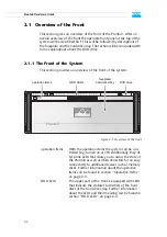
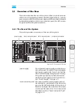
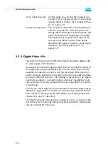
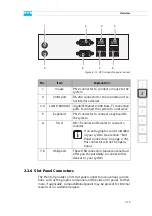
ATX connector panel
On this panel you can find the standard con-
nectors of the computer system. It is described
in more detail in section “ATX Connector Pan-
el” on page 2-14.
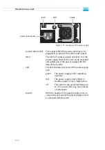
slot panel connectors The slot panel connectors of the Pronto3 pro-
vide, for example, the video I/O panel con-
taining video connections and the graphic card
panel. Furthermore, if applicable, some addi-
tional panels may be present for internal rea-
sons or on customer request. More details
about the slot panel connectors can be found
in section “Slot Panel Connectors” on
page 2-15.
Summary of Contents for Pronto3
Page 1: ...Pronto3 Hardware Guide Version 1 0 Digital Disk Recorder Pronto3 Hardware Guide ...
Page 2: ......
Page 6: ......
Page 8: ......
Page 36: ...2 18 Pronto3 Hardware Guide ...
Page 38: ...3 2 Pronto3 Hardware Guide ...
Page 68: ...A 16 Pronto3 Hardware Guide ...
Page 72: ...I 4 Pronto3 Hardware Guide VTR 1 1 warranty 1 7 XLR connectors audio 2 13 ...


