background image


Page 2 of 20 


Table of Contents 


Safety Instructions ………………………………………………………..……………………………… 

Cautions….. ............................................……………………………………………………………….. 

Introduction.....…………………………………………………………………………………………….. 

Programming SL-8000 Remote Control to Operate PlasmaImage HD-50……...……………..… 

Connections …………………..……………….………………………………………………………….. 

Installation ……………….…..……………………………………………………………………………. 

Quick Reference Remote Control Operation ..................……………………………………………  10 

The Front Panel Controls................................………..………………………………………………..

Information Menu……………………….………………….……………………………………………… 

11 

11 

Using The Control Menus.................................…………..……………………………………………  12 


Main Menu ..........................................……………….………………………………………….  12


Input Option.........................................………………..………………………………………….  12 


Format Option...........................................………….……………………………………………  12 


Video Control Menu..................................………….……………………………………………  13 


Setup Menu .........................................…………….…………………………………………….  13 


Menu Timeout..............................……………………………………………………….. 


Color Temp………………………………………………………………………………… 

13 
13 


Screen Saver………………………………………………………………………………. 

Sidebars……………………………………………………………………………………. 

Menu Position……………………………………………………………………………… 

Rename Inputs.............................……………………………………………………….. 

14 
14 

14 
15 


Rename Ratios……….......................…………………………………………………… 

15 


Image Setup..............................…………………………………………………………. 

15 


New Video Source………………………………………………………………………… 

16 


Relay Setup.

.....................................……………………………………………………

16 


Power Button 

Setup...................…………………………………………………………. 

16 

PlasmaImage HD-50 RS-232 Control .....................…………………………….………….…………  17 

Specifications ..........................................……………………………………………………..………..  18 

Warranty ................................................………………………………………………………..……….  19 


Summary of Contents for PlasmaImage HD-50

Page 1: ...f 20 Video Systems PlasmaImage HD 50 Operating Instructions Read these instructions completely before operating this unit Contents subject to change without notice or obligation PlasmaImage 1 1 Printe...

Page 2: ...ion 10 The Front Panel Controls Information Menu 11 11 Using The Control Menus 12 Main Menu 12 Input Option 12 Format Option 12 Video Control Menu 13 Setup Menu 13 Menu Timeout Color Temp 13 13 Screen...

Page 3: ...Never place this product near or over a radiator or heat register Do not place this product in a built in installation such as a bookcase or rack unless proper ventilation is provided 8 Operate only...

Page 4: ...he blades can be fully inserted to prevent blade exposure NOTE This equipment is designed to operate in the USA Canada and other countries where the broadcasting system and AC house current is exactly...

Page 5: ...unique separate component design provides the most flexible connectivity by allowing the Digital Video Processor to be conveniently located near all the video sources while the Plasma Display is moun...

Page 6: ...nputs S1 S2 4 pin Mini Din 7 Composite Video Inputs V1 V2 RCA Type 8 Component Video Inputs Y1 R1 B1 RCA Type Y2 R2 B2 RCA Type 9 AC Power Receptacle 3 Prong Receptacle 1 DIGITAL OUTPUT Note The Plasm...

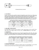
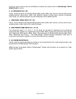
Page 7: ...5V Power 22 Clock Shield 6 DDC Clock 15 Ground 23 Clock 7 DDC Data 16 Hot Plug Detect 24 Clock 9 Data 1 17 Data 0 3 SWITCHED 12VDC OUTPUTS The PlasmaImage Processor has two switched 12 VDC outlets la...

Page 8: ...VCR and DVD players 8 COMPONENT VIDEO INPUTS Y1 Y2 Y3 Two component video Y Cr Cb or Y Pr Pb inputs are provided for interlaced and non interlaced component video signals from regular DVD players 480...

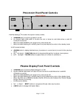
Page 9: ...to turn the PlasmaImage On or Off A green indicator light which is lit when the unit is turned on and blinks when a valid IR command is received When the LED is DARK the AC power to the unit is turned...

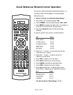
Page 10: ...ON or OFF Press MENU to display the Main menu to advance a sub menu or to return to the previous menu Use the numbered buttons for direct switching of inputs To select a specific input press a numbere...

Page 11: ...the previous menu Up and down FUNCTION buttons to sequences through the on screen menu options Left and right VALUE buttons to adjust values or to move to a sub menu Plasma Display Front Panel Control...

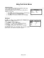
Page 12: ...he remote to clear the screen immediately Information Input D V I 2 Format HD Video Type 720p Main Menu The Main menu offers a choice of Input selection Format selection Video controls and Setup funct...

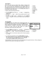
Page 13: ...o of played video signal For example a DVD player which is connected to the Y B R input may be used to playback either Standard 4 3 format or Letterbox format Format selection is provided for 480i 480...

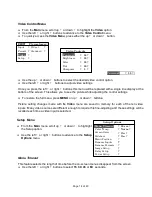
Page 14: ...you to see the picture while adjusting the control settings To restore the full menu press MENU or up or down buttons Picture setting changes made with the Video menu are saved in memory for each of...

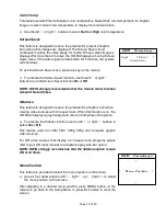
Page 15: ...t the Screen Saver function remain ON at all times Sidebars This feature is designed to reduce the potential for phosphor burn when viewing video sources with 4 3 aspect ratio When this function is on...

Page 16: ...t the process for all of the inputs you wish to rename Rename Formats The Formats refers to the aspect ratio of played video signal For example a DVD player which is connected to the Y B R input may b...

Page 17: ...ft or right buttons to select Yes Press ENTER Relay Setup The Relay Setup allows you to assign the PlasmaImage s RY1 and RY2 screen trigger outputs to particular aspect ratio for screen masking Off Re...

Page 18: ...d is enclosed in the character envelope Note Sequential commands must be separated with proper delays Any command followed by POWER ON must be delayed 10 seconds Any command followed by INPUT SELECT m...

Page 19: ...cessories Fixed 5 degree tilt Wall Mount Adjustable 15 degree tilt Wall Mount 19 inch Rack Mount Kit for Video Processor Proprietary DVI Cables 25 30 35 40 45 and 50 foot lengths 2 foot DVI D Adapter...

Page 20: ...om installation related circumstance such as signal quality AC power or incompatibilities with display devices or computer software This warranty specifies the acceptable pixel defect standards of the...

Reviews: