T5L_ASIC Development Guide
- 16
-
www.dwin-global.com
DWIN Technology
Professional,
Creditable,
S
uccessful
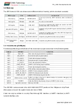
3.2.2 Variable Memory(256KBytes)
(1) 0x00:0000-0x00:7FFF addresses correspond to the 128Kbytes variable memory space currently
used by the DGUS II system.
For example, the two DGUS II variable memories, 0x1000 and 0x1001, correspond to the 0x0800
address of the OS 8051 DGUS variable memory, where D3 corresponds to the 0x1000 variable high
byte and D2 corresponds to the 0x1000 variable low byte; D1 corresponds to 0x1001 variable high
byte and D0 corresponds to 0x1001 variable low byte.
(2) 0x00:8000-0x00:FFFF addresses are not used by DGUS II system at present, and can be defined
by users as variable memory.
(3) 0xFF:0060-0xFF:006B address, the configuration and transceiver buffer of CAN interface.
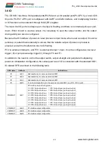
Access to the DGUS variable memory uses the SFR register interface in the following table.
SFR name
Address
Instruction
RAMMODE
0xF8
DGUS variable memory access interface control, which can be bit addressed.
.7 Write 1=request occupation of DGUS variable memory to read/write. Must be cleared when not
occupied.
.6 APP_EN Write 1=initiate read/write once. It is cleared after hardware execution.
.5 APP_RW 1=Read variable memory 0=Write variable memory
.4 APP_ACK Hardware answer to 8051 request to occupy variable memory, 1=OK, 0=BUSY.
.3-.0 Corresponding to DATA3:DATA0 Write enable 1=corresponding bytes written, 0=corresponding
byte not written.
ADR_H
0XF1
DGUS variable memory high 8-bit address,A23:A16.
ADR_M
0XF2
DGUS variable memory middle 8-bit address,A15:A8.
ADR_L
0XF3
DGUS variable memory low 8-bit address,A7:A0.
ADR_INC
0xF4
The automatic increment of address after reading and writing of DGUS variable memory.
That is, ADR_H:M:L after reading and writing = ADR_H:M:L+ADR_INC before.
DATA3
0xFA
DGUS variable data interface, write selection corresponds to RAMMODE.3.
DATA2
0XFB
DGUS variable data interface, write selection corresponds to RAMMODE.2.
DATA1
0XFC
DGUS variable data interface, write selection corresponds to RAMMODE.1.
DATA0
0XFD
DGUS variable data interface, write selection corresponds to RAMMODE.0.
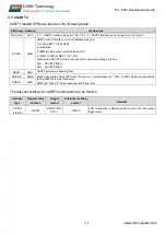
DGUS variable memory must be read and written according to the steps below.(If you want to use
interrupt in the application, the interrupt must be closed when the main application reads and writes
DGUS variable data, not embedded.)
(1) Configured address and address increment;
(2) Set RAMMODE as 0x8F (write) or 0xAF (read), check if RAMMODE. 4=1 to confirm access to
read and write control.
(3) Read and write data, set RAMMODE as 0X00 after reading and writing.

