background image

10

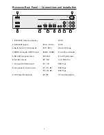
7. COMPOSITE VIDEO INPUTS (V1, V2)

The V1 and V2 inputs are provided for NTSC (480i) or PAL (580i) video sources, 
such as off-air tuners, satellite systems, cable boxes, VCR and DVD players.  

8. COMPONENT VIDEO INPUTS (Y1, Y2, Y3)

Two component video Y, Cr, Cb or Y, Pr, Pb inputs are provided for interlaced 
video signals from regular DVD players (480i, 580i), progressive component 
video signals from progressive DVD players (480p, 580p), and progressive or 
interlaced HD signals (480p, 540p, 720p, 1080i) from HD sources. The TransVi-
sion

 3E Processor automatically detects the resolution and configuration of 

the component video signal applied to its input and processes it accordingly. 

9. AC POWER RECEPTACLE

The AC power receptacle should be connected to a non-switched 120 VAC outlet 
using the power cord provided with the TransVision

 3E system.

DWIN strongly recommends that the TransVision

 3E Projector and Proces-

sor both be connected to the same AC line circuit using a high quality surge 
protector or power line conditioner. 

Summary of Contents for TransVision 3 Enhanced

Page 1: ...TransVision 3 Enhanced TransVision 3 Enhanced 1 1 Printed in USA...

Page 2: ......

Page 3: ...ration 12 Navigating The Control Menus 14 Information Menu 14 Main Menu 14 Input Option 15 Format Option 15 Video Control Menu 16 Setup Options 17 Menu Timeout 17 Menu Position 17 Rename Inputs 18 Ren...

Page 4: ...ces may cause the appliance and a cart to overturn 7 Side Top and Bottom openings in the cabinet are provided for ventila tion and to insure reliable operation of the video equipment and protect it fr...

Page 5: ...een spilled into the video equipment 15 3 If the video equipment has been exposed to rain or water 15 4 If the video equipment does not operate normally by following the operating instructions 15 5 Ad...

Page 6: ...rgy and if not installed and used in accordance with the instructions may cause harmful interference to radio communication However there is no guarantee that harmful interference will not occur in a...

Page 7: ...amp status between the Projector and the Processor An infrared learning wireless remote control with on screen graphics selects the input source and adjusts all of the operating controls The system ma...

Page 8: ...is connected and the unit is in the standby mode When the LED is on the unit is powered on When the LED is ashing fast this indicates that the lamp failed to ignite If the lamp failed to ignite the la...

Page 9: ...3 Switched 12 VDC Outputs RY1 RY2 2 5mm DC Plug 4 RGBS Computer HDTV Inputs RGB1 RGB2 D sub 15 pin Socket 5 RS 232 Computer Input RS 232 D sub 9 pin Socket 6 S Video Inputs S1 S2 4 pin Mini Din 7 Comp...

Page 10: ...x the xx refers to the length of the cable For cable lengths longer than 50 feet use DWIN s Cable Extender The cable extender operates with DVI R xx cables and are available in 25 35 and 50 Feet lengt...

Page 11: ...ck 7 DDC Data 16 Hot Plug Detect 24 Clock 9 Data 1 17 Data 0 The following are the pin assignments for the DVI D connectors Pin No Signal Name Pin No Signal Name Pin No Signal Name 1 Red 6 Ground 11 2...

Page 12: ...ers 480p 580p and progressive or interlaced HD signals 480p 540p 720p 1080i from HD sources The TransVi sion 3E Processor automatically detects the resolution and con guration of the component video s...

Page 13: ...remote control 1 Press the TV device button 2 Press and hold both the SHIFT and ENTER buttons for 3 seconds The display will blink Set and then DWIN 3 Enter the TransVision 3E brand code 177 4 Press t...

Page 14: ...12 1 2 3 4 5 6 7 8 9 1 0 0 ENT MODE SUB CTR REAR SELECT AUD CD DVD AUX SAT MUTE MENU EXIT GUIDE INFO PREV CH TV VCR OFF TV VCR SHIFT CBL LIGHT DWIN ON VOL CH Quick Reference Remote Control Operation...

Page 15: ...own to sequence through the on screen menu options 7 Press left or right to adjust values or to navigate to sub menus 8 Press SEL to advance to a sub menu 9 Press EXIT to clear the on screen menus 10...

Page 16: ...enu offers a choice of Input selection or Format selection and navigation options to Video controls and Setup functions 1 Press MENU to display the Main menu 2 Scroll up or down the list to highlight...

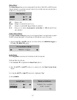
Page 17: ...trol for direct switching of inputs Format Option The Format option refers to the aspect ratio of the recorded video For example a DVD player which is connected to the component input may be used to p...

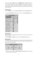
Page 18: ...e settings are recalled for each input and video type when selected Video Control Menu 1 From the Main menu scroll up or down to highlight the Video option 2 Use the left right or SEL buttons to advan...

Page 19: ...p Options Menu Timeout 30 sec Menu Position Norm Rename Inputs On Rename Formats On Num Buttons Input Screen Setup Image Setup Custom Format Relay Setup Power Setup Lamp Hours Menu Timeout This featur...

Page 20: ...alpha numeric options Scrolling up starts with the letter A and continues to the end of the alpha bet followed by numbers and punctuation marks Scrolling down repeats the process in exactly the oppos...

Page 21: ...selections Screen Setup Mounting Front Floor Image Setup The Image Setup menu allows you to position and adjust the video input im age size Video image parameters vary from different video sources and...

Page 22: ...p and 1080i video sources Video sources recorded in a 4 3 aspect ratio will appear with black bars along the left and right sides on the screen To reduce or eliminate these black bars you can use the...

Page 23: ...he Power Button Setup allows you to select between a single button power On Off or separate power On and power Off buttons on your remote 1 Use the left or right buttons to select either the POWER Tog...

Page 24: ...three dimensional physical adjustments made possible by the mounting hardware for size using the zoom ring of the lens for vertical offset to adjust the image up or down rotate the Lens Shift Wheel l...

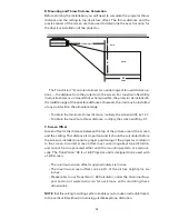
Page 25: ...e their heads from side to side As a rule of thumb the viewing distance should not be less than two times the screen width For example if your home theater has a 100 inch wide screen you should have y...

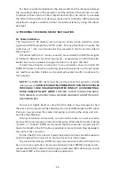
Page 26: ...hrow distance multiply the screen width by 2 1 C Screen Offset Screen offset is the distance between the top of the picture area of the screen and the ceiling This distance is important and it should...

Page 27: ...in advance for this purpose NOTE The DWIN DVI cable must be used to connect the projector and the videoprocessor DWINSTRONGLYRECOMMENDSTORUNTHEDVICABLES THROUGH A 1 INCH OR LARGER DIAMETER CONDUIT A C...

Page 28: ...er cables slightly to the front and left side of the center of the projector 2 In rooms where the projector is mounted near a rear wall be sure to allow adequate clearance for proper ventilation Allow...

Page 29: ...weight of the projector and mount which is approximately 25 pounds A1 C1 C2 B2 B1 A2 Ceiling Mount Kit Ceiling Bracket A Ceiling Bracket B Ceiling Assembly C Do Not Remove Hex Nuts 1 Disassemble the C...

Page 30: ...with the FRONT label facing toward the lens NOTE DO NOT ATTEMPT TO LOOSEN THE FIVE HEX NUTS ON THE CEILING AS SEMBLY C THEY ARE SEALED 7 Use provided four 0 4 countersink screws to attach the ceiling...

Page 31: ...on this sensor should not be covered C NOTE The TransVision 3E requires the use of a DWIN DVI cable between the Projector and the Digital Video Processor to operate correctly D The POWER LED is a mult...

Page 32: ...n the right side To shift the image the to the right tighten the hex screw on the left side Once desired position is obtained tighten both screws To level the projector front back loosen both the B1 a...

Page 33: ...31 Physical Dimensions TransVision 3E 13 5 4 5 4 5 14 2 0 5 0 A A A A A CEILING MOUNT HOLE LOCATION 5 2 AC Input Circular Connector...

Page 34: ...Note Sequential commands must be separated with proper delays Any command followed by POWER ON must be delayed 10 seconds Any command followed by INPUT SELECT must be delayed 1 second The following t...

Page 35: ...h Diagonal Throw Distance 1 41 to 2 1 times Screen Width Projection Offset Lens Level to 40 of Picture Height Light Source 200 Watt VIP Lamp Lamp Life 2000 Hours Contrast 3000 1 INPUTS DVI Proprietary...

Page 36: ...32 Serial 1x D 9 Pin RS 232 Compatible AC Power 3 Prong Receptacle OUTPUTS DVI 1 x DVI D with HDCP 12V Triggers 2 x 2 5mm DC Plug Power Source 100 130 VAC Power Consumption 25 Watts Dimensions WxDxH 1...

Page 37: ...uctions damage from the performance of repairs by someone not authorized by DWIN Electronics any unit on which the serial number has been effaced modified or removed damage occurring during shipment a...

Page 38: ...present the original bill of sale to establish the date of purchase Limited 90 Day Warranty Projector Lamps TransVision 3E lamps are rated for up to 2 000 hours of use during which the lamp brightness...

Page 39: ...r SERVICE DEPARTMENT DWIN Electronics Inc 710 North Mariposa St Burbank CA 91506 Tel 818 239 1500 Fax 818 239 1506 Warranty Procedure for Replacement Lamps To receive a replacement lamp even under war...

Reviews: