background image

- 19 of 23 -


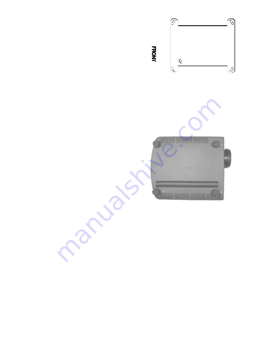
When the projector is floor mounted, the use of the mounting hardware is not required. However, you
will need to calculate the throw distance and screen offset as shown in the previous section.

For floor mount installations remember to
calculate the offset from the bottom of the picture
to the floor. If the projector is mounted inside a
cabinet and NOT placed directly on the floor, the
offset is the distance between the bottom of the
projector’s feet and the bottom of the picture.

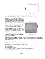
When the unit is floor mounted, a 1” rubber tube
must be attached to the bottom of the projector in
order to block hot air circulation inside the unit.

Attach the supplied rubber tube near the “out” vent
on the right side of the projector so that exhaust
air is properly channeled out of the unit and away
from the floor.

When the unit is mounted inside a cabinet, be
certain that an exhaust vent is provided so that the
hot air generated by the projector may be safely
removed from the cabinet.

                            Air in


Air out

                     For  Floor mount

Before completing the installation, double check all screws, mounting hardware and the projector feet to
make certain that they are securely tightened so that no further movement of the projector/mounting
assembly is possible.

After the physical mounting is complete, horizontal and vertical adjustments are made to center and
align the projected image to the screen. The white field pattern, as described in 

Screen Set-Up

 menu

section, is used to make the three dimensional adjustments.

Before these dimensional adjustments can be made, you must:

q


Turn system on.

q


Adjust the zoom and focus.

q


Once on screen menus can be clearly viewed, go to 

Screen Set-Up

 menu.

q


Select the proper screen aspect ratio.

Make the following horizontal and vertical adjustments to align the white field pattern to the screen:


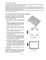
Ceiling bracket C

Summary of Contents for TransVision

Page 1: ...TransVision Operating Instructions Read these instructions completely before operating this unit Contents subject to change without notice or obligation Printed in USA TransVision Rev 7...

Page 2: ...ain Menu 10 Input Option 10 Aspect Ratio Option 11 Video Control Menu 11 Setup Menu 12 Menu Timeout 12 Rename Inputs 12 Rename Ratios 13 Screen Setup 13 Image Setup 14 New Video Source 14 Relay Setup...

Page 3: ...this product near or over a radiator or heat register Do not place this product in a built in installation such as a bookcase or rack unless proper ventilation is provided 8 Operate only from the typ...

Page 4: ...e this appliance to rain or moisture To prevent electric shock do not use this polarized plug with an extension cord receptacle or other outlet unless the blades can be fully inserted to prevent blade...

Page 5: ...players 480i 580i progressive DVD players 480p 580p and HD 480p 540p 720p 1080i sources Two RGB inputs are provided for HD 480p 580p 720p 1080i sources and computer graphics with VGA SVGA and XGA reso...

Page 6: ...ter Inputs 15 pin HD Socket 4 RS 232 Computer Input 9 pin D Plug 5 S Video Inputs S1 S2 4 pin Mini Din 6 Composite Video Inputs V1 V2 RCA Type 7 Component Video Inputs Y1 Cr1 Cb1 RCA Type Y2 Cr2 Cb2 Y...

Page 7: ...ed for use with DVD players and satellite systems For these inputs the system provides source switching contrast brightness color tint and sharpness controls and amplifies S video signals to allow the...

Page 8: ...TROL inputs should be connected to the matching connectors on the TransVision s Controller using high quality coaxial cables with BNC connectors Note that ALL FIVE connections must be made for proper...

Page 9: ...ansVision ON or OFF q Press MENU to display the Main menu or to return to the previous menu q Use the numbered buttons for direct switching of inputs To select a specific input press a numbered button...

Page 10: ...An indicator light which is lit when the unit is turned on and blinks when a valid IR command is received USING THE CONTROL MENUS Main Menu The Main menu offers a choice of input selection aspect rat...

Page 11: ...ALT 1 for 4 3 Std press ALT 2 for anamorphic press ALT 3 for letterbox DWIN TRANSVISION Input Setup Video Video 1 Aspect Ratio Letterbox 1 4 x 3 STD 2 Anamorphic 3 Letterbox Once an aspect ratio is s...

Page 12: ...the length of time before the on screen menus disappear from the screen q Use left or right a buttons to select 15 30 45 or 60 seconds Rename Inputs This feature is for changing Input names which appe...

Page 13: ...d vertical position of the prospective projected image for the 16 9 or 15 9 screen aspect ratio To Select the Aspect Ratio of Your Screen q Select the Screen option in the Screen Options menu q Use th...

Page 14: ...sVision selects video image settings from the system s memory The predefined video sources include 480i 480p 580i 580p 1080i 540p and 720p In addition to predefined video sources the TransVision allow...

Page 15: ...d To Reset the Lamp Hours q Scroll down to highlight the Reset option q Use left or right a buttons to advance to the Reset Lamp Hours menu q Use left or right a buttons to select Yes q Press ENTER La...

Page 16: ...sition and preparation including drilling holes and assembling the mounting hardware 3 Installation of the ceiling mount bracket and placing the projector in the mount Once the physical installation i...

Page 17: ...according to the aspect ratio of the screen and the screen width For screens with a 4 3 aspect ratio the offset is within a range of approximately six to eight inches For screens with a 16 9 or 15 9...

Page 18: ...hen secure the two pieces together using the four hex head screws provided making certain that the FRONT marking facing the screen q Place two center screws on both left and right sides of the part B...

Page 19: ...the unit is mounted inside a cabinet be certain that an exhaust vent is provided so that the hot air generated by the projector may be safely removed from the cabinet Air in Air out For Floor mount Be...

Page 20: ...loosen hex screws on the left and right side of ceiling mount and tilt projector Once desired position is obtained refasten all four hex screws q To align image parallel to the screen loosen hex screw...

Page 21: ...Any command followed by POWER ON must be delayed 10 seconds Any command followed by INPUT SELECT must be delayed 1 second The following table lists the commands available POWER CONTROL PON power on P...

Page 22: ...C 220 Watt Auto Switch power supply Projection Offset For 4 3 screen 6 to 8 from the lens center For 16 9 adjustable from 6 to 25 of screen height Controller 45 Watt 100 130 VAC or 200 250 VAC Factory...

Page 23: ...ng during shipment units which have been altered or modified in design appearance or construction This warranty covers only the actual defects within the PRODUCT itself and DOES NOT cover the costs of...

Reviews: