- 6 of 23 -
Programming SL-8000 Remote Control to Operate the TransVision™
The TransVision™ is shipped with a factory pre-programmed remote control.
q
To program the SL-8000 for TransVision™:
1. Press the
TV
and the
MUTE
buttons simultaneously.
SET
will appear on the LCD.
2. Enter the TransVision™’s brand code:
177
.
3. Press
TV
to complete the programming.
To operate other audio and video devices refer to the
“SL-8000
Operating Manual.”
Installation of the Controller
115 VAC 60 Hz
65 WATTS MAX.
2
2
/
RED
GREEN
BLUE
+12 VDC
100 mA
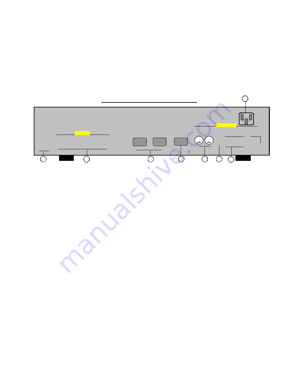
TransVision™ Controller Rear Panel
1
2
3
1
1
1
1
V1
V2
Y1
Y2
VIDEO INPUTS
4
RGBS
2
INPUT
2
1
1
1
1
Cr1
Cr2
Cb1
Cb2
5
7
6
RS232
CONTROL
"
"
"
"
"
"
"
"
S1
S2
/
RY1
RY2
2
2
SYNC
CONTROL
OUTPUTS
1
1
1
1
Y3
Y3
Cr3
Cb3
RGBS
1
INPUT
"
"
"
"
"
"
"
"
"
"
"
"
"
"
"
"
"
"
"
"
"
"
"
"
"
"
"
"
"
"
"
"
"
"
"
"
"
"
"
8
1.
Sw12VDC Outputs, RY1, RY2
2.5mm DC Plug
2.
Red, Green, Blue, Sync and Control Outputs BNC
3.
RGBS Computer Inputs
15 pin HD Socket
4.
RS-232 Computer Input
9 pin D Plug
5.
S-Video Inputs ( S1, S2 )
4 pin Mini-Din
6.
Composite Video Inputs ( V1, V2 )
RCA Type
7.
Component Video Inputs (Y1, Cr1, Cb1)
RCA Type
(Y2, Cr2, Cb2)
(Y3, Cr3, Cb3)
8.
AC Power Receptacle .
1. SW12VDC OUTPUTS
The TransVision™ has two sw12 VDC outlets labeled as RY1 and RY2. These outlets may be
used to trigger a relay in an electric screen, projector lift or other relay activated device. See “
Relay
Setup
” menu for more details.
2. RED, GREEN, BLUE, SYNC & CONTROL OUTPUTS
The output video signal from the Controller to the DLP
™
projector is made by five 75 Ohm coaxial
cables with BNC connectors for RED, GREEN, BLUE, SYNC and CONTROL outputs. The CONTROL
cable is used to transmit bi-directional control signals between the projector and the Controller unit. The
CONTROL cable must be connected in order for the system to function properly.
q
To test the connection:
1. Press
INFO
on the remote.
The screen will display either “Controller connected” or “Controller not connected.”
3. RGBS INPUTS


