13
English
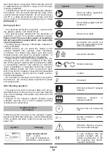
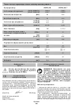
Symbol
Meaning
Attention. Important.
Useful information.
Do not dispose of the power
tool in a domestic waste
container.
DWT
power tool designation
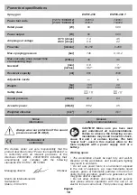
This power tool is designed for spraying and applying
liquid materials on a treated surface. It allows the user
to apply paints, varnishes, primers, preservatives,
protective and disinfectant materials, as well as to
spray water for wetting surfaces.
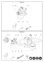
1
Power tool
components
Nozzle
2
Air cap
3
Coupling nut
4
Button
5
Reservoir
6
Spray volume regulator
7
Air hose
8
Cover
9
On / off switch
10
Spray gun holder
11
Base unit
12
Measuring funnel *
13
Cleaning rod *
14
Carrying belt *
15
Purge nozzle *
16
Ventilation slots
17
Flexible extension hose *
18
Tube
19
Nut
20
Lock nut
21
Discharge opening
22
Tip for connection to the base unit
23
Tip for connection of accessories
24
Filter
25
Suction hole
26
Drain hole
27
Air filter *
* Optional extra
Not all of the accessories illustrated or described
are included as standard delivery.
Installation and regulation
of power tool elements
Before carrying out any works on the power tool it
must be disconnected from the mains.
Do not draw up the fastening elements
too tight to avoid damaging the thread.
Mounting / dismounting / setting-up of
some elements is the same for all power
tool models, in this case specific models
are not indicated in the illustration.
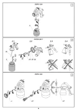
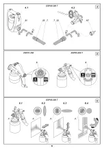
Reservoir connection / disconnection (see fig. 1-2)
Connect / disconnect reservoir
5
as shown on
figures 1-2.
[ESP05-200 T]
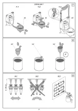
Prior to connecting reservoir
5
, turn tube
18
(see
fig. 2.2) into the position allowing maximum use up of
the material. It depends on where the spray gun will be
tilted during operation (see fig. 2.3-2.4).
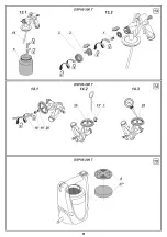
•
Loosen the lock nut
20
and unscrew the nut
19
.
•
Turn the tube
18
to the required position.
•
Screw the nut
19
and secure it by tightening the lock
nut
20
.
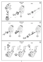
Flexible extension hose connection / disconnection
(see fig. 3)
[ESP01-250]
• Flexible extension hose
17
allows spraying material
onto horizontal surfaces as well as in hard-to-reach
places (for example, when painting heating radiators).
•
Unscrew nozzle
1
(see fig. 3).
• Screw flexible extension hose
17
on, then bend it
into the required position.
•
In order to disconnect, perform these steps in
reverse order.
Air hose connection / disconnection (see fig. 4)
[ESP05-200 T]
•
Connect the air hose
7
to the base unit
11
. Insert the
tip
22
into the opening
21
after aligning the protrusions
on the tip
22
with the grooves in the hole
21
. Rotate the
tip
22
as shown on figure 4.1.
•
Connect the air hose
7
to the spray gun or the
purge nozzle
15
. Place the tip
23
on the shank of the
accessory by pre-aligning the grooves in the tip
23
with
the protrusions on the accessory. Rotate the tip
23
as
shown on figure 4.2.
•
In order to disconnect, perform these steps in
reverse order.
Initial operating
of the power tool
Always use the correct supply voltage: the power
supply voltage must match the information quoted on
the power tool identification plate.
Switching the power
tool on / off
[ESP01-250]
Switching on:
Press and hold button
4
.
Summary of Contents for 742654
Page 1: ......
Page 4: ...4 ...
Page 5: ...5 ...
Page 6: ...6 ...
Page 7: ...7 ...
Page 8: ...8 ...
Page 9: ...9 ...
Page 44: ...44 ...
Page 45: ...45 ...
Page 46: ...46 ...
Page 47: ...47 ...
Page 48: ...48 ...
Page 49: ...49 ...
Page 50: ...50 ...
Page 51: ...51 ...
Page 52: ...52 ...
Page 53: ...53 ...
Page 69: ...69 ...
Page 70: ...70 ...
Page 71: ......
Page 72: ...72 ...
Page 73: ...73 ...
Page 74: ...74 ...
Page 75: ...75 ...
Page 76: ......


