background image

9

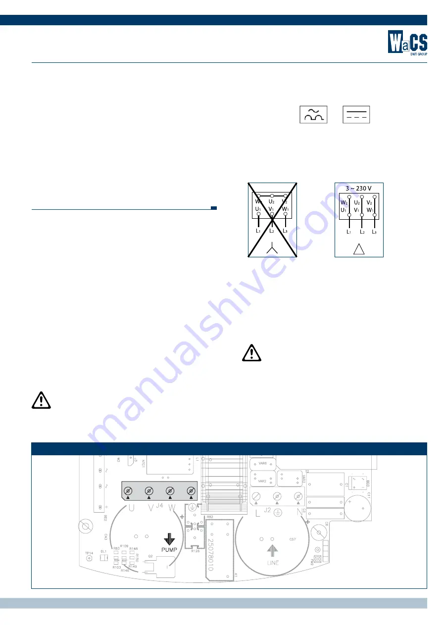
The  delta  connection  is  the  one  typically  used  for  working  at  230 V 
(lower voltage). PWMs are normally supplied complete with cable for 
connection to the motor.
For versions not supplied with the cable, the connection is on the 4-way 
terminal “J4” (3  earth) marked “PUMP” and with the arrow on 
output. The minimum cable section must be 1.5 mm

2

Incorrect connection of the earth lines to a terminal other than 
the earth terminal may cause irremediable damage to the whole 
appliance!
Incorrect  connection  of  the  power  supply  line  on  output  termi-
nals intended for the load may cause irremediable damage to the 
whole appliance!

Conexión a la línea de alimentación

Conectar el PWM a la línea de alimentación. En caso de prolongamiento 
del cable de alimentación, utilizar un cable de sección adecuado para 
limitar la caída de tensión total (alimentación más bomba) al 3%. En 
cualquier caso non utilizar cables de sección menor de 1,5 mm2
En caso de prolongamiento de los cables del inverter, por ejemplo en 
las alimentaciones de electrobombas sumergidas, si se presentan tras-
tornos electromagnéticos, es oportuno:
1.  Comprobar la conexión a tierra y eventualmente añadir un disper- 
  sor de tierra en los alrededores del PWM.
2.  Enterrar los cables.
3. Utilizar cables blindados.
4. Instalar los siguientes filtros de red.

El  PWM  ya  dispone  de  protecciones  de  corriente.  Si  dispone  de  un 
magnetotérmico en línea, tiene que tener una capacidad adecuada a 
la bomba utilizada.
La conexión de la línea al PWM incluirá la línea de tierra. La resistencia 
de tierra total no deberá superar 100  Ohm. 

Aconsejamos la instalación de un interruptor diferencial 
para proteger la instalación que se adapte correctamente, 

del tipo: Clase A (AS para los modelos con alimentación trifásica), 
con la corriente de dispersión regulable, selectivo, protegido con-

tra  disparos  inoportunos.  El  interruptor  diferencial  automático 
tendrá que estar marcado con los dos símbolos siguientes:

Conexión de la bomba 

La  tensión  de  alimentación  del  motor  de  la  electrobomba  instalada 
tiene  que  ser  230V  trifásica.  Las  máquinas  eléctricas  trifásicas  dis-
ponen normalmente de 2 tipos de conexión tal como se muestra en 
Figura 3 y Figura 4

La conexión a triángulo es típicamente la que se utiliza para trabajar a 
230V (tensión menor). Normalmente los PWM disponen de cable para 
la conexión al motor.
Para versiones que no disponen de cable, la conexión se efectúa sobre 
el borne “J4” de 4 vías (3 fases + tierra) con serigrafía “PUMP” y con 
la flecha en salida. El cable tiene que disponer de una sección mínima 
de 1.5 mm

2


La  conexión  incorrecta  entre  las  líneas  de  tierra  y  un 
borne que no sea el de tierra puede dañar todo el aparato 

irremediablemente!
La conexión incorrecta entre la línea de alimentación y los bornes 
de salida destinados a la carga puede dañar todo el aparato ir-
remediablemente!

Morsetto di uscita elettropompa trifase


Three-phase electro pump output terminal 

- Borne de salida de la electrobomba trifásica

Conexión errónea

4


Conexión correcta

WACS si riserva il diritto di apportare modifiche senza obbligo di preavviso - 

WACS reserves the right to make any changes it deems fit without notice

 - WACS se reserva el derecho de realizar modificaciones sin la obligación de aviso previo 

Summary of Contents for WaCS PWM 230

Page 1: ...le phase power supply but internally creates a three phase 230V voltage Moreover the D version can communicate with other PWMs without additional control panels or other external devices floatswitch 2nd pressure set point emergency stop button and status of the PWM E g 2 PWMs D 10 5 can be easily assembled with a standard cable in a very compact 2 pump booster set with changeover and exchange The ...

Page 2: ......

Page 3: ...utto in uno sensore di flusso e di pressione integrati Facile installazione Possibilità di creare gruppi di pressurizzazione con interscambio Constant pressure Reduced power consumption of up to 60 Built in protections Operates with all pumps Installed directly on the pump outlet All in solution with integrated flow and pressure sensor Easy to install Facility to create booster units with changeov...

Page 4: ...o variations in rpm Pump rpm n has a very significant influence on pump performance In the absence of cavitation phenomena the law of similarity is applicable as shown in equation 1 Flow rate changes in a linear manner with changes in speed Pressure changes in a squared relationship with changes in rpm Power changes in a cubed relationship with changes in rpm A small change in rpm produces a very ...

Page 5: ...8 Kg 3 8 Kg Posizione di lavoro Work position Emplazamiento de trabajo Qualunque Any position Cualquiera Qualunque Any position Cualquiera Qualunque Any position Cualquiera Max temperatura del liquido Max fluid temperature Máx temperatura del líquido 50 º C 50 º C 50 º C Max temperatura ambiente Max ambient temperature Máx temperatura ambiente 60 º C 60 º C 60 º C Pressione max Max pressure Presió...

Page 6: ...mpre dell acqua Nota Se il PWM viene scollegato dall alimentazione la funzione antigelo non può più assolvere il suo compito Pericolo corpi estranei nella tubazione la presenza di sporco all interno del fluido può ostruire i canali di passaggio o bloccare la valvola di flusso e pregiudicare il corretto funzionamento del sistema Nel caso il PWM venga installato su una tubazione attraverso la quale ...

Page 7: ...i di elettropompe sommerse se si hanno disturbi elettro magnetici è opportuno 1 Verificare la messa a terra ed eventualmente aggiungere un disper sore di terra nelle immediate vicinanze del PWM 2 Interrare i cavi 3 Usare cavi schermati 4 Installare dei filtri di rete Il PWM è già provvisto di protezioni di corrente Se è installato un magnetotermico in linea questo deve avere una portata adeguata a...

Page 8: ...is required use a cable with a suitable section to limit possible overall voltage drops power supply plus pump to 3 In any event never use cables with a section of less than 1 5 mm2 In the case of extensions to the inverter cables for example for power supply to submersed electric pumps if there is electromagnetic distur bance the following is recommended 1 Check earthing and if necessary add an e...

Page 9: ...resistencia de tierra total no deberá superar 100 Ohm Aconsejamos la instalación de un interruptor diferencial para proteger la instalación que se adapte correctamente del tipo Clase A AS para los modelos con alimentación trifásica con la corriente de dispersión regulable selectivo protegido con tra disparos inoportunos El interruptor diferencial automático tendrá que estar marcado con los dos sím...

Page 10: ...s The text rC is displayed The value rC is read on the dataplate of the electric pump as the rated current in Ampere A and is entered using the keys and 2 Setting the direction of rotation Press 2 time mode key The text rt is displayed after which use keys and to invert the direction of pump rotation Open a valve to start up the pump and check the direction of rotation 3 Setting the operating pres...

Page 11: ...er A good pressure set point is between 1 3 and 2 3 of the maximum pump pressure head This serves to maintain a high level of pump ef ficiency while maximising power savings Note The PWM inverter does not stop the pump if the pressure value is not reached although a flow is detected This strategy prevents service outages in the case of high flow applica tions La curva de las prestaciones añadiendo...

Page 12: ...g and releasing the and keys simultane ously If the error condition persists it is necessary to remove the cause of the anomaly In case of overcurrent the protection acts in two ways Maximum frequency limiting as temperature increases over a poten tially dangerous value The second type of protection is used on power devices supply capacitor printed circuit It acts when a potentially dangerous temp...

Page 13: ...ue to overheating of the printed circuit Bloqueo por sobre calentamiento del circuito estampado Si ripristina quando la temperatura del circuito stampato scende sotto i 100 C Reset when the temperature of the printed circuit falls below 100 C again Se restablece cuando la temperatura del circuito estampado desciende por debajo de los 100 C OC Blocco per sovracorrente Shutdown due to current over l...

Page 14: ...pump If the pressure is lower than the set point one the display shows a lack of water mes sage If you wrongly set a pressure set point higher than the pressure that the electro pump is able to supply the system will sign lock due to lack of water bL even if there is no lack of water So you should lower the set point pressure at a reasonable value that usually does not exceed 2 3 of the of the ins...

Page 15: ... ATTENZIONE Se non si collegano prima le terre si rischia di danneg giare gli apparati Using the 4 7 A PWM 230 or the 10 5 A PWM 230 booster sets of up to 2 pumps equipped with communication can be created First of all connect the inverters electrically as shown in figure 10 Note Connect the two inverters to earth before you start connecting the communication cables CAUTION If you proceed without ...

Page 16: ...ene visualizzato Il valore di Eb può essere modificato con i tasti e Eb 1 In questa modalità funzionerà una sola pompa per volta anche se non fosse in grado di soddisfare la richiesta Eb 2 Default In questa modalità si ha la possibilità di accendere la seconda pompa se la prima non fosse in grado di soddisfare l utenza Dopo avere impostato il dato premere il tasto SET per tornare al menù principal...

Page 17: ...ulsando durante 5 segundos los botones y pulsando el botón MODE varias veces hasta que se visualice El valor Ad puede modificarse con los botones y En el primer PWM hay que configurar 1 En el segundo PWM hay que configurar 2 Después de haber configurado el dato pulse el botón SET para volver al menú principal Después de estas operaciones los PWM se comunican con configuraciones adecuadas para la m...

Page 18: ...float switch Choose a second pressure Enable or disable the inverter Switch on a light when the inverter is running Switch on a light when the inverter returns an error Todos los PWM 230 salvo el modelo PWM 230 3 BASIC están equi pados con 3 entradas y 2 salidas Dichas conexiones pueden utilizarse para conectarse a sistemas de control remoto para Conectar un flotador Elegir una segunda presión Hab...

Page 19: ...hen IN 2 is enabled the set point pressure becomes P1 see sec 5 1 3 9 2 I2 Setting function of inlet 2 active set point selection SP or P1 SEGUNDA PRESIÓN Cuando se activa IN 2 la presión de regulación se vuelve P1 véase el párr 5 1 3 9 2 I2 Configuración de la función entrada 2 con mutación setpoint activo SP o P1 Alimentazione tensione continua oppure tensione alternata Direct Voltage supply or ...

Page 20: ...s y configuraciones de la asistencia técnica teclas MODE y SET y 5 segundos tb Impostazione del tempo di latenza del blocco mancanza acqua in s Setting the reaction time of the water low block in s Configuración del tiempo de espera del bloqueo por falta de agua en s 10 s 10 s 10 s T1 Tempo di running dopo il segnale di bassa pressione Running time after low pressure signal Tiempo de running tras ...

Page 21: ...ctric pump phase current inA Visualización de la corriente de fase de la electrobomba enA rt Impostazione del senso di rotazione Setting the direction of rotation Configuración del sentido de rotación UF Visualizzazione del flusso Display of flow Visualización del flujo ZF Visualizzazione dello zero flusso Display of zero flow Visualización de cero flujo Reset di sistema tasti MODE e STE e e _ Sys...

Page 22: ...8 2 3685 2 5295 RISPARMIO ANNUALE YEARLY SAVING AHORRO ANUAL 2 59 kWh X 365 946 kWh 946 kWh X 0 2 E kWh E 188 94 Nella tabella si mettono a confronto i consumi giornalieri di una pom pa standard pilotata da sistema on off e di una gestita da inverter PWM Come si vede in una giornata di medio utilizzo PWM permette di rag giungere un risparmio di 2 59 kWh pari al 60 rispetto al consumo di una tradiz...

Page 23: ......

Page 24: ...onanno Pisano 1 Bientina PI Italy Phone 39 0587 753800 Fax 39 0587 488815 www wacs it 03 2011 60144178 DWT HOLDING S p A Sede Legale Headquarter Via Marco Polo 14 35035 Mestrino Padova Italy www dwtgroup com ...

Reviews: