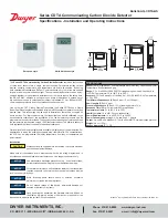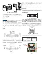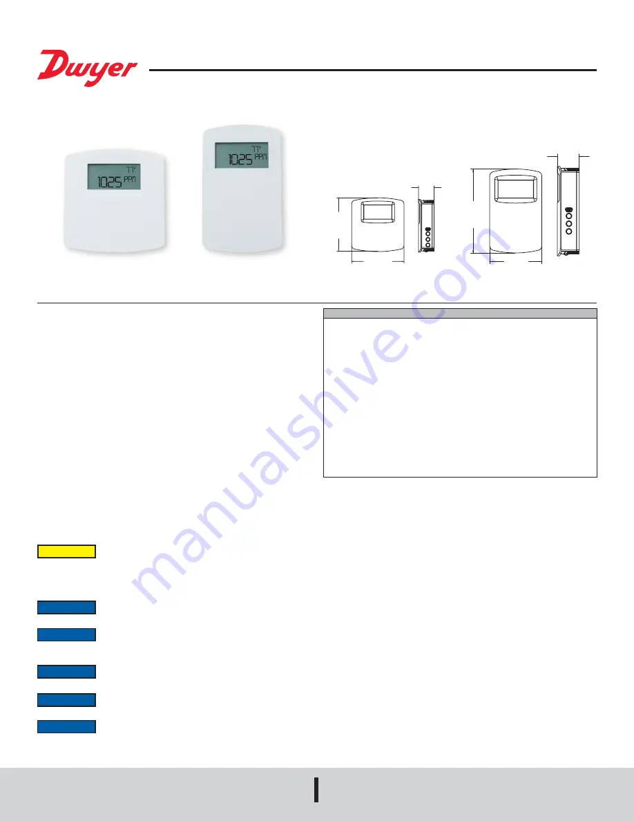
Series CDTA Communicating Carbon Dioxide Detector
Specifications - Installation and Operating Instructions
Bulletin AQ-CDTA-QS
The
Series CDTA Communicating Carbon Dioxide Detector
combines the function
of three room sensors into a single, compact housing. Parameters include carbon
dioxide, humidity, temperature, and temperature set point with override. By having
field selectable Modbus® and BACnet Communications, only four wires are needed
for power and the communication signal. The communicating detectors can be daisy-
chained together to further reduce installation cost. In order to reduce the set up time,
the RS-485 MAC address is set up using on board dip switches. A second set of
dip switches are used to select whether output is Modbus® RTU or BACnet MS/TP
communication protocols and to limit access to the set up menu.
Like our Series CDT Carbon Dioxide Transmitter, the Series CDTA uses a Single
Beam Dual Wavelength Non-Dispersive Infrared (NDIR) sensor to measure the carbon
dioxide level. This technology can be used in installations that will be occupied 24
hours per day. For improved accuracy, the transmitter can be field calibrated to the
environmental conditions of the installation. Also, the barometric pressure can be
programmed to correct for altitude. The humidity uses a capacitive polymer sensor and
the temperature is measured using a 10KΩ thermistor sensor. The humidity sensor is
field replaceable without the need for additional calibration.
Optional local and remote displays are available to display any of the parameters. For
applications in which the building occupants aren’t familiar with CO
2
concentrations,
the LCD can be programmed to display temperature, humidity, or temperature set
point instead.
Installation
SPECIFICATIONS
Sensor (CO
2
):
Single-beam, dual-wavelength NDIR; Humidity: Capacitive polymer;
Temperature: Solid state band gap.
Range:
CO
2
: 0 to 2000 or 5000 PPM CO
2
(depending on model); Humidity: 0 to
100% RH; Temperature: 32 to 122°F (0 to 50°C).
Accuracy:
CO
2
: ±40 ppm ±3% of reading; RH: ±2% (10 to 90% RH); Temperature:
±1°C @ 25°C.
Temperature Dependence (CO
2
):
±8 ppm / °C at 1100 ppm.
Non-Linearity (CO
2
):
16 ppm.
Pressure Dependence (CO
2
):
0.13% of reading per mm of Hg.
Response Time (CO
2
):
2 minutes for 99% step change.
Temperature Limits:
32 to 122°F (0 to 50°C).
Humidity Limits:
10 to 95% RH (non-condensing).
Power Requirements:
10 to 42 VDC / 10 to 30 VAC.
Power Consumption:
Average: 0.5 watts; Peak: 1.2 watts.
Output:
2-wire RS-485, Modbus
®
RTU or BACnet MS/TP communication protocol.
Weight:
4.4 oz (125 g).
Agency Approvals:
BTL, CE.
European style
North American style
1.08
[27.33]
1.10
[27.96]
4.50
[114.30]
2.80
[71.12]
3.65
[92.72]
3.56
[90.42]
Use electrostatic discharge precautions (e.g., use of wrist straps)
during installation and wiring to prevent equipment damage.
For optimal performance, self calibration feature of the transmitter
requires exposure to normal outdoor equivalent carbon dioxide
level once every thirty days.
Avoid locations where severe shock or vibration, excessive
moisture or corrosive fumes are present.
Do not exceed ratings of this device, permanent damage not
covered by warranty may result.
Upon powering the transmitter, the firmware version will flash on
the display. A warm up period of 30 minutes is required for the
transmitter to adjust to the current CO
2
concentration.
NOTICE
NOTICE
NOTICE
NOTICE
NOTICE
Disconnect power supply before installation to prevent electrical
shock and equipment damage.
Make sure all connections are in accordance with the job wiring diagram and in
accordance with national and local electrical codes. Use copper conductors only.
CAUTION
Modbus
®
is a registered trademark of Schneider Automation, Inc.
®
DWYER INSTRUMENTS, INC.
P.O. BOX 373 • MICHIGAN CITY, INDIANA 46360, U.S.A.
Phone: 219/879-8000
Fax: 219/872-9057
www.dwyer-inst.com
e-mail: info@dwyermail.com

