background image

Bulletin B-32

Series DH Digihelic

®

Differential Pressure Controller

Specifications - Installation and Operating Instructions

DWYER INSTRUMENTS, INC. 

Phone: 219/879-8000     www.dwyer-inst.com

P.O. BOX 373 • MICHIGAN CITY, IN 46361, U.S.A.           

Fax: 219/872-9057         e-mail: info@dwyer-inst.com

B-32:B-32  7/9/09  2:52 PM  Page 1

www.calcert.com

sales@calcert.com

1.888.610.7664

0

5

10

15

20

25

30

Summary of Contents for DH-002

Page 1: ...Installation and Operating Instructions DWYER INSTRUMENTS INC Phone 219 879 8000 www dwyer inst com P O BOX 373 MICHIGAN CITY IN 46361 U S A Fax 219 872 9057 e mail info dwyer inst com B 32 B 32 7 9 09 2 52 PM Page 1 www calcert com sales calcert com 1 888 610 7664 0 5 10 15 20 25 30 ...
Page 2: ...2 91 28 1 15 16 49 21 3 25 32 96 04 Face Designed to Meet NEMA 4X IP66 PANEL CUT OUTS Horizontal 3 620 in 0 032 0 0 92 00 mm 0 8 0 0 1 772 in 0 024 0 0 45 00 mm 0 6 0 0 B 32 B 32 7 9 09 2 52 PM Page 2 www calcert com sales calcert com 1 888 610 7664 0 5 10 15 20 25 30 ...

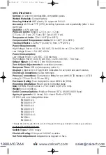
Page 3: ... 250 ms dampening set to 1 Display 4 digit LCD 0 4 height LED indicators for set point and alarm status Electrical Connections Screw terminals Process Connections Compression fitting for use with 1 8 ID tubing x 1 4 OD tubing 3 175 mm ID x 6 35 mm OD Enclosure Rating Face designed to meet NEMA 4X IP66 Mounting Orientation Mount unit in horizontal plane Size 1 8 DIN Panel Cutout 1 772 x 3 620 in 45...

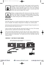
Page 4: ...essure Port NOTES 1 The instrument may be powered from the AC line or 24 VDC Do not wire AC line terminals 4 5 and 24 VDC terminals 14 15 at the same time or damage to the unit will result 2 For supply connections wire in accordance with an equivalent national standard or code Use copper conductors only rated for at least 75 C 3 Terminals 11 15 18 and 20 are rated CLASS 2 4 ISOLATION Relays 1500 V...

Page 5: ... installing From the rear of the panel slide the mounting collar over the housing Hold the hous ing with one hand and using the other hand push the collar evenly against the panel until the springs are compressed The ratchets will hold the mounting collar and housing in place C 20 20 19 19 18 18 17 17 16 16 15 15 14 14 13 13 11 11 12 12 10 10 9 8 7 6 5 4 3 2 1 21 21 22 22 23 23 24 24 20 20 19 19 1...

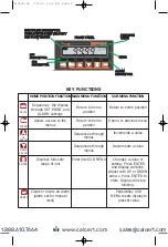
Page 6: ...gh SET POINT and ALARM settings Allows access to the menus Displays full scale range of unit Clears or resets an Alarm alarm set for manual reset MAIN MENU FUNCTION Return to home position Return to home position Sequences through menus Sequences through menus Enter into SUB MENU SUB MENU FUNCTION Return to home position Return to previous menu Increments a value Decrements a value Changes a value...

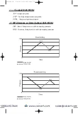
Page 7: ...d deadband simply adjust SP1H or SP2H for the desired relay turn on point and then adjust SP1L or SP2L for the desired relay turn off point PRESSURE PRESSURE 0 0 TIME TIME 0 2 0 2 0 4 0 4 0 6 0 6 0 8 0 8 1 0 in w c In the above graph an instrument with a 1 0 range would have the SP1 relay turn on at 0 8 and off at 0 4 SP1H sets the relay turn on point and SP1L sets the relay turn off point The rel...

Page 8: ...GS MAIN MENUS SUB MENUS MENUS UNAVAILABLE FOR BI DIRECTIONAL RANGES AND RANGES ABOVE 25 IN W C SP AL MENU E RST SP AL MENU E RST SP AL MENU E SP AL MENU MENU B 32 B 32 7 9 09 2 52 PM Page 8 www calcert com sales calcert com 1 888 610 7664 0 5 10 15 20 25 30 ...

Page 9: ...NTINUED SETTINGS SETTINGS MAIN MENUS SUB MENUS SP AL MENU E RST SP AL MENU E RST SP AL MENU E RST SP AL MENU MENU E B 32 B 32 7 9 09 2 52 PM Page 9 www calcert com sales calcert com 1 888 610 7664 0 5 10 15 20 25 30 ...

Page 10: ...NUS SETTINGS Menus present only in pressure operation SP AL MENU E RST SP AL MENU E RST SP AL MENU E RST SP AL MENU MENU E RST B 32 B 32 7 9 09 2 52 PM Page 10 www calcert com sales calcert com 1 888 610 7664 0 5 10 15 20 25 30 ...

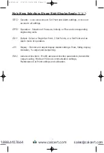
Page 11: ...t a Single Set Point 2 Set Points or a Set Point and an Alarm mode of operation d S Display Monitor and adjust display related settings Peak Valley display resolution output and dampening AdU Advanced functions Modify advanced function parameters transmitter output scaling Modbus Protocol communication settings Maintenance Set Point settings and calibration B 32 B 32 7 9 09 2 52 PM Page 11 www cal...

Page 12: ...he instrument is set for Velocity the OPEr MENU will have an additional KFAC SUB MENU If the instrument is set for Flow the OPEr MENU will have additional KFAC and ArEA SUB MENUS These will be discussed under Velocity and Flow When scrolling through the OPEr SUB MENUS the measurement type the unit is currently set for will show the units in the upper right display The other measure ment types will...

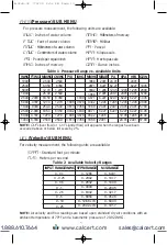
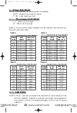
Page 13: ...ity measurement the following units are available SFPM Standard feet per minute M S Meters per second Table 2 Available Velocity Ranges NOTE Air velocity and flow readings are based upon standard dry air conditions with an ambient temperature of 70 F and a barometric pressure of 29 92 INHG INPUT RANGE INWC 0 0 1 0 0 25 0 0 5 0 1 0 2 5 0 5 0 10 0 25 SFPM RANGE 0 1266 0 2002 0 2832 0 4004 0 6332 0 8...

Page 14: ...cturer may specify a K Factor The adjustment range is 0 01 to 2 00 The factory setting is 1 Table 4 FLOr HI Maximum Duct Size English RANGE IN WC 0 1 0 25 0 5 1 2 5 5 10 25 SCFM RANGE 999 9 x 1K 999 9 x 1K 999 9 x 1K 999 9 x 1K 999 9 x 1K 999 9 x 1K 999 9 x 1K 999 9 x 1K MAX DUCT SIZE SQ FT 789 8 499 5 353 1 249 7 157 9 111 7 78 9 49 9 Table 5 FLOr LO Maximum Duct Size Metric RANGE IN WC 0 1 0 25 ...

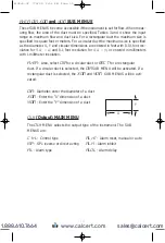
Page 15: ...in millimeters with 1 millimeter resolution ArEA Area select CIR for a circular duct or RECT for a rectangular duct If a circular duct is selected the DIA SUB MENU will be activated If a rectangular duct is selected the XDIM and YDIM SUB MENUS will be acti vated DIA Diameter enter the diameter of a duct XDIM Enter the X dimension of a duct YDIM Enter the Y dimension of a duct OUt Output MAIN MENU ...

Page 16: ...nts SPAL Single set point and alarm 1SP SP1 Reverse or Direct Acting SUB MENU DIR Direct Relay turns on with increasing pressure REV Reverse Relay turns on with decreasing pressure 0 100 Process Direct Acting Time SPH SPL Relay Inactive Relay Active B 32 B 32 7 9 09 2 52 PM Page 16 www calcert com sales calcert com 1 888 610 7664 0 5 10 15 20 25 30 ...

Page 17: ...rm Low Alarm or High Low Alarm Alarm settings are all absolute and may be set to anywhere within the range of the instrument The dead bands of the alarms are fixed at 1 of full scale MIN PRESSURE MAX PRESSURE ALHI Relay OFF Relay ON HIGH ALARM FUNCTION MIN PRESSURE MAX PRESSURE ALLO Relay ON Relay OFF LOW ALARM FUNCTION MIN PRESSURE MAX PRESSURE ALLO Relay ON Relay OFF Relay ON HIGH LOW ALARM FUNC...

Page 18: ...lay MAIN MENU PEAK Peak value rESO Resolution VALy Valley value Pd S Process display ZERO Zero DAMP Dampening level PEAK Peak SUB MENU The Peak feature stores the highest pressure reading the instrument has measured since the last reset or power up At power up PEAK is reset to the present pressure reading To manually reset the PEAK value press the RESET key while in the PEAK SUB MENU VALy Valley S...

Page 19: ...stabilities due to things such as vibration and excessive pressure fluctuations The dampening setting adjusts the amount of readings that are averaged for each display update Adjust the dampening value until the display reads a stable value for the application AdU Advanced MAIN MENU POL Process output low ADDR Modbus Protocol address POH Process output high WR Modbus Protocol write enable disable ...

Page 20: ...O and SPAN Calibration of Zero and Span SUB MENUS The lower display reads CAL in this mode ZERO Calibration NOTE For accurate calibration DO NOT apply any pressure when performing this function With the display reading ZERO press the ENTER key The upper display will blink Press ENTER again to complete the zeroing of the instrument or press the MENU key to cancel SPAN Calibration With the display s...

Reviews: