background image

6&+(0$7,&6*(1(5$/$1',175,16,&6$)(7<

1.  Units supplied with switch option A, G, H, M or T 
    have screw terminals on the back side of the switch 
    for terminating wires.
2.  UL and CSA units    supplied with switch option D are  

  VXSSOLHGZLWK´PLQLPXPPHWHUVÀ\LQJOHDGV

3.  Units supplied with switch option B, C, I, R, S, V or 

  :DUHVXSSOLHGZLWKWHUPLQDOVWULSVRUÝPLQLPXP
  PHWHUVÀ\LQJOHDGV
 8QLWVZLWK-RU-VXI¿[DUHVXSSOLHGZLWKDGGLWLRQDO

    2 or 4 termination points.

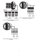
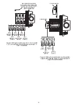
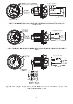
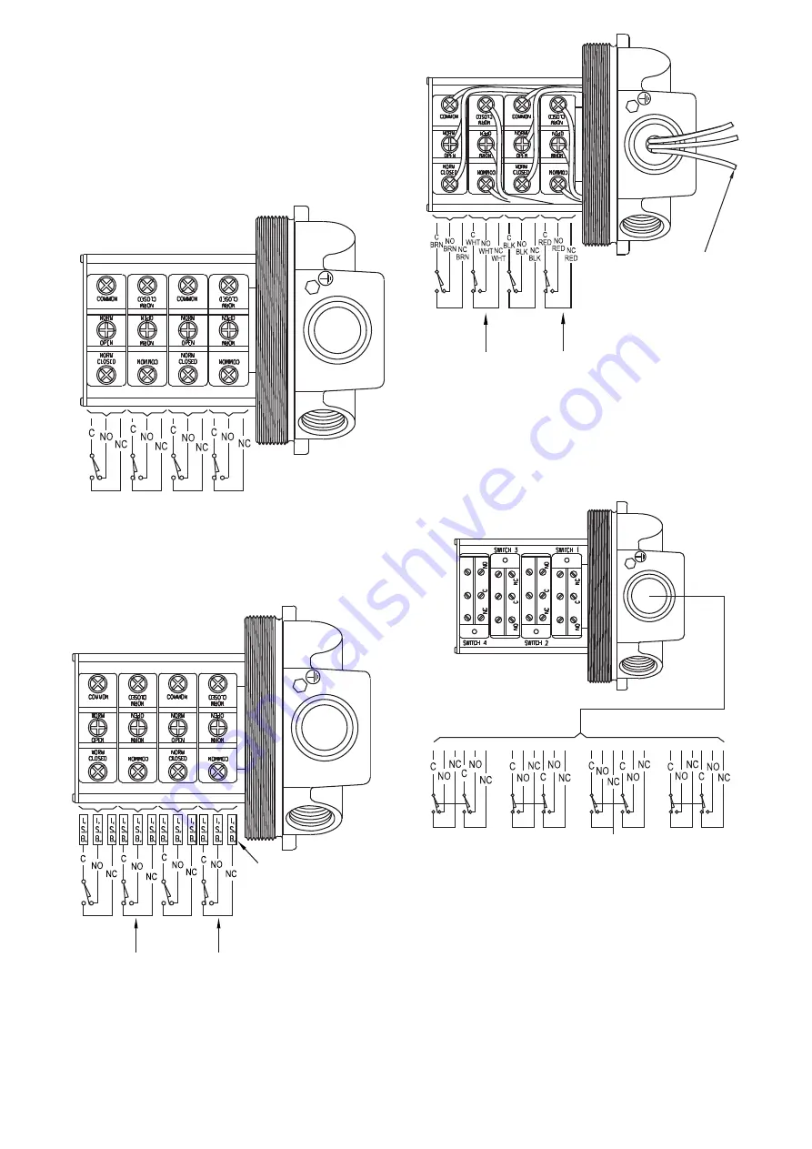
)LJXUH:LULQJIRUVZLWFKW\SHV$*+0DQG7

RUVZLWFKHV

)LJXUH,QWULQVLFDOO\VDIHZLULQJIRUVZLWFKW\SHV$

*+0DQG7RUVZLWFKHV

)LJXUH:LULQJIRUIDFWRU\VHDOHGOHDGVRSWLRQ

RUVZLWFKHV6ZLWFKZLUHVDUHUHGVZLWFK

ZLUHVDUHEODFNVZLWFKZLUHVDUHZKLWHDQGVZLWFK

ZLUHVDUHEURZQ:LUHVDUHODEHOHG&121&

)LJXUH:LULQJIRUVZLWFKW\SH'RU

switches

SW 4

TOP

SWITCH

SW 3

ABOVE 

2ND

SWITCH

SW 2

ABOVE 

1ST

SWITCH

SW 1

BOTTOM

SWITCH

INTRINSICALLY 

SAFE BARRIERS

SW 4

TOP

SWITCH SW 3

ABOVE 2ND

SWITCH

SW 2

ABOVE 1ST

SWITCH SW 1

BOTTOM

SWITCH

SWITCH 4

TOP 

SWITCH

SWITCH 3

ABOVE 2ND 

SWITCH

SWITCH 2

ABOVE 1ST 

SWITCH

SWITCH 1

BOTTOM 

SWITCH

SW 4

ABOVE 3RD

SWITCH

SW 3

ABOVE 2ND

SWITCH

SW 2

ABOVE 1ST

SWITCH

SW 1

BOTTOM

SWITCH

GREEN WIRE 

- GROUND

Summary of Contents for PROXIMITY Series

Page 1: ...aled switches and high current switches Aside from switch outputs the Mark Series offers potentiometer outputs 4 20 mA transmitters and HART communication The units are purchased for either direct drive applications such as rotary valves or lever drive applications such as linear valves For the Mark 1 3 and 4 this instruction manual starts with installation of the unit to the device being monitore...

Page 2: ...V WKDW DUH Ý PP RI RQGXLW RQQHFWLRQ 6WDQGDUG RQH Ý IHPDOH 137 RSWLRQDO RQH WR WZR Ý IHPDOH 137 2SWLRQDO 0 1 5 or M20 X 1 5 connections may be supplied in lieu of Ý DQG Ý IHPDOH 137 IRU DOO PRGHOV 0RXQWLQJ 2ULHQWDWLRQ Not position sensitive HLJKW WR OE WR NJ 2SHUDWLRQDO LIH Over 10 000 000 cycles 0D LPXP OWLWXGH 2000 meters 5000 meters for PRGHOV IROORZHG E RU followed by A B C G I T V or W CLEARAN...

Page 3: ...DWXUH LPLWV WR WR 7 ÀDPHSURRI VXI DQG ÀDPHSURRI VXI UDWHG WR WR IRU VZLWFK W SHV 0 2 5 6 7 9 RU WR WR IRU VZLWFK W SHV RU 7 LQWULQVLFDOO VDIH 6 VXI DQG LQWULQVLFDOO VDIH VXI UDWHG WR WR IRU VZLWFK W SH WR WR IRU VZLWFK W SHV 2 5 6 9 RU 3RZHU 5HTXLUHPHQWV 5 30 VDC XUUHQW RQVXPSWLRQ 50 mA 2XWSXW 6LJQDO 4 20 mA HUR DQG 6SDQ GMXVWPHQWV 7ULP SRWV IRU DGMXVWLQJ ERWK 0DUN DQG 6SDQ LV DGMXVWDEOH IURP WR 0...

Page 4: ...es B I R W Transmitter with HART communication Available with switches see QRWH EHORZ A A A A A A A A A A A A A A A A A A A A A A A A A A A A A A A A A A A A A A A A A A A A Switch Type and Rating A B C D G H I M O R S T V W 63 7 VQDS UDWHG 9 a KS 9 a KS 9 a 9 9 Inductive sensor 10 30 VDC Load 0 1 A 63 7 KLJK WHPSHUDWXUH VQDS IRU KRXUV UDWHG 9 a 3 7 VQDS UDWHG 9 a 9 0 15 A 250 VDC 63 7 JROG FRQWDF...

Page 5: ...rminal strip DWWDFKHG VROHQRLG YDOYH PXVW EH RUGHUHG ZLWK RSWLRQ DWWDFKHG VROHQRLG YDOYHV PXVW EH RUGHUHG ZLWK RSWLRQ Metric threaded conduit connection M25 X 1 5 M20 X 1 5 for optional J1 and J2 connections LUHFWLYH 8 0 7 2813 GE 7 E 7DPE GHSHQGLQJ RQ RXWSXW switch type selected LUHFWLYH 8 0 7 2813 ia IIC T4 Ga GE 7 E 7DPE GHSHQGLQJ RQ RXWSXW DQG VZLWFK W SH VHOHFWHG LD 7 D 3OXJ SRUWV 7 DQG XQLWV...

Page 6: ... long 02817 1 76 Mounting kits are available for direct installation of the Proximity Controls Mark Series onto most valve and actuator brands Proximity Controls has over 2000 kits available and can custom make kits for any application DFK NLW LV VSHFLDOO GHVLJQHG IRU D SDUWLFXODU DFWXDWRU RU YDOYH PDNLQJ HOG PRXQWLQJ VLPSOH ZLWK VWDQGDUG WRROV Mounting kits can be used with any model in the Mark ...

Page 7: ... or power and observe that drive shaft and drive yoke are concentric and perpendicular LQ FRPSOHWH VWURNH GMXVW SRVLWLRQ DV UHTXLUHG DQG tighten all the mounting screws Check concentricity DQG SHUSHQGLFXODULW 5HDGMXVW SHU DERYH VWHSV DV necessary GMXVWPHQW 3URFHGXUH A Using a wrench or power rotate the actuator shaft to extreme clockwise position All switches should change to their opposite functi...

Page 8: ...XDO FDPV DQG ZLOO EH GLUHFWO above index marks on those switches that are Closed Marks must be in line when making switch FDP DGMXVWPHQWV DPV DUH VHW DW IDFWRU ZKHQ LQ the counterclockwise position as shown and listed as follows 2 Switch Unit 1 Open 2 Closed 4 Switch Unit 1 3 Open 2 4 Closed 6ZLWFK 8QLW 2SHQ ORVHG WUDYHO LQ FORFNZLVH GLUHFWLRQ ZLOO UHYHUVH DOO RI above switch positions GMXVWPHQW 3...

Page 9: ...or A will add three revolutions for each location moved until 13 revolutions are required between switch 1 and 2 actuation 3 The cam screw for switch 2 in location A By moving LW WR ORFDWLRQ RU WKUHH UHYROXWLRQV DUH added for each location change 4 Rotate the switch slowly through the full cycle several times before tightening the bolts securely Observe the rotation for signs of yoke or shaft misa...

Page 10: ...er 7R DGMXVW WKH SRWHQWLRPHWHU WR D GLIIHUHQW UDQJH loosen the two lower set screws on the coupling While holding the cams in the desired position rotate the coupling and potentiometer shaft to the preferred location Rotating clockwise reduces resistance between pins 2 and 1 and increases resistance between 2 and 3 Rotating counterclockwise increases resistance between pins 2 and 1 and reduces res...

Page 11: ...VWPHQW LQVWUXFWLRQV p 7 for Direct Drive Mark 1 and 4 Models p 8 for Lever Drive Mark 1 and 4 Models p 9 for Mark 3 Models 2 Remove cover by unscrewing Take care to keep threads clean and free from damage 3 On models 15XXX and 45XXX the switches are set at the factory when in the counterclockwise position as shown Switch 1 is open and 2 is closed When FDPV DUH URWDWHG FORFNZLVH EHFRPHV FORVHG DQG ...

Page 12: ...LGGOH RI its range Full multi turn range is 25 revolutions set DW UHYROXWLRQV 5HSHDW FDOLEUDWLRQ VWHSV and D 6HH 3DJHV for wiring procedure intrinsic safety parameters relevant warnings and schematics 0 5 1 75 160 77 5 7 57 20081 7 21 167 7 21 Models 19XXX 39XXX and 49XXX Rotary Position Indicating Switches contain a 4 20 mA transmitter with HART communication and two Single Pole Double Throw SPDT...

Page 13: ...VHW WR 2 WKH transmitter will ignore FIND commands This is useful for allowing a HART communication master to discover the transmitter 7KH ZLOO ÀDVK LQ UHVSRQVH WR D 57 FRPPXQLFDWLRQ PDVWHU V 6TXDZN RPPDQG 7KLV LV useful for identifying a transmitter attached to a HART communication master DOLEUDWLRQ A Place the WP shunt in the OFF position in necessary to allow calibration to be performed B Set t...

Page 14: ...KDOO EH XVHG 21 8 7 211 7 21 Q 8 RU 6 ZLWK DSSURSULDWH FODVVHV DQG JURXSV FHUWL HG ÀDPHSURRI VHDOLQJ GHYLFH VXFK DV D conduit seal with setting compound shall be provided immediately following the conduit entrance to the enclosure UL and CSA listed factory sealed leads are provided from the factory on request RU DPELHQW WHPSHUDWXUHV DERYH WKH ZLULQJ DQG setting compound in the conduit seal shall b...

Page 15: ...conçues pour une utilisation en atmosphère SRWHQWLHOOHPHQW GDQJHUHXVHV DX VHLQ GH O 8QLRQ XURSpHQQH HV XQLWpV SHXYHQW rWUH HVWDPSLOOpHV SRXU G DXWUHV LUHFWLYHV GH O 8QLRQ XURSpHQQH 9 6 21 6 1 5 86 6 1 8 DLVVHU OH FRXYHUFOH ELHQ IHUPp ORUVTXH O XQLWp HVW HQ service RXSHU OH FLUFXLW G DOLPHQWDWLRQ DYDQW G RXYULU Q G HPSrFKHU WRXWH LJQLWLRQ GDQV GHV RQHV dangereuses replacer le couvercle avant de met...

Page 16: ...U VZLWFKHV LJXUH QWULQVLFDOO VDIH ZLULQJ IRU VZLWFK W SHV 0 DQG 7 RU VZLWFKHV LJXUH LULQJ IRU IDFWRU VHDOHG OHDGV RSWLRQ RU VZLWFKHV 6ZLWFK ZLUHV DUH UHG VZLWFK ZLUHV DUH EODFN VZLWFK ZLUHV DUH ZKLWH DQG VZLWFK ZLUHV DUH EURZQ LUHV DUH ODEHOHG 12 1 LJXUH LULQJ IRU VZLWFK W SH RU switches SW 4 TOP SWITCH SW 3 ABOVE 2ND SWITCH SW 2 ABOVE 1ST SWITCH SW 1 BOTTOM SWITCH INTRINSICALLY SAFE BARRIERS SW 4...

Page 17: ...U VZLWFK W SHV 5 9 DQG RU VZLWFKHV SWITCH 4 TOP SWITCH SWITCH 3 ABOVE 2ND SWITCH SWITCH 2 ABOVE 1ST SWITCH SWITCH 1 BOTTOM SWITCH INTRINSICALLY SAFE BARRIERS SW 4 TOP SWITCH SW 3 ABOVE 2ND SWITCH SW 2 ABOVE 1ST SWITCH SW 1 BOTTOM SWITCH SW 4 TOP SWITCH SW 3 ABOVE 2ND SWITCH SW 2 ABOVE 1ST SWITCH SW 1 BOTTOM SWITCH INTRINSICALLY SAFE BARRIERS ...

Page 18: ...5HIHU WR QRWH DW ERWWRP RI SDJH IRU VZLWFK GHWDLOV LJXUH LULQJ IRU VZLWFK W SHV 5 9 DQG RU VZLWFKHV 6ZLWFK W SHV DQG KDYH DQG WHUPLQDOV SW 6 ABOVE 5TH SWITCH SW 5 ABOVE 4TH SWITCH SW 4 ABOVE 3RD SWITCH SW 3 ABOVE 2ND SWITCH SW 2 ABOVE 1ST SWITCH SW 1 BOTTOM SWITCH USE CONNECTOR SUPPLIED WITH SWITCH ONLY MAKE SURE CONNECTOR IS PUSHED ON ALL THE WAY TO ASSURE A TIGHT CONNECTION ...

Page 19: ...MATIC SEE WIRING SCHEMATIC WIRING SCHEMATIC BY OTHERS 12 VDC OR 24 VDC SW 4 TOP SWITCH SW 3 ABOVE 2ND SWITCH SW 2 ABOVE 1ST SWITCH SW 1 BOTTOM SWITCH LJXUH QWULQVLFDOO 6DIH ZLULQJ IRU SRWHQWLRPHWHU RXWSXW 5HIHU WR SURSHU VZLWFK JXUH LI XQLW KDV VZLWFKHV DV ZHOO LJXUH QWULQVLFDOO 6DIH ZLULQJ IRU WUDQVPLWWHU RXWSXW 5HIHU WR SURSHU VZLWFK JXUH LI XQLW KDV VZLWFKHV DV ZHOO LJXUH QWULQVLFDOO 6DIH ZLULQ...

Page 20: ...gs label is removed or if the instrument or equipment is abused altered used at ratings above the PD LPXP VSHFL HG RU RWKHUZLVH PLVXVHG LQ DQ ZD Substitution of components may impair intrinsic safety of models with 6 RU 0 VXI HV 8VH D GDPS FORWK ZLWK VRDS DQG water for cleaning and decontamination Solvents may damage O ring seals Units in need of repair should be returned to the following address ...

Reviews: