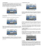
2.1 WIRING ELECTRICAL BOX (ROUGH IN)
Layout the system in terms of wiring: power, analog output, BACnet, relay output,
digital inputs, analog inputs and plumbing to connect to the monitored spaces. Run all
power, earth ground, signal communications and analog output wiring into the RSMC
junction box. Follow all local electrical codes and refer to the wiring diagrams on this
page and the back label of the RSMC for proper terminal locations.
The RSMC includes one digital output which may be wired to a local audible or visual
alarm or may be wired to a controller to indicate an alarm condition. The RSMC contains
one analog output that linearly corresponds to the reading of the built-in pressure
sensor. The RSMC contains 2 built-in analog inputs. The analog inputs are capable of
accepting 4-20 mA, 0-5 VDC, or 0-10 VDC analog transmissions. The analog inputs
may be assigned as differential pressure, temperature, relative humidity, or air change
per hour (ACH). One analog input can also be assigned as a digital input for use as a
door status indicator. This input setup is performed in the input/output menu.
Power supply minimum requirements:
EN 55032 CISPR 32
FCC Part 15 Subpart B
2.2 ATTACHING PRESSURE TUBING
Use 1/8˝ or 3/16˝ (3 mm or 5 mm) ID rubber or vinyl tubing (adapters as necessary) to
transition from any pre-installed tubing to the barbed pressure fittings on the RSMC.
For the most stable pressure operation, an room pressure pickup installed in the
reference pressure area is also recommended.
For measuring a room maintaining a positive pressure, connect one end of tubing to
the room pressure pickup in the room and the other end to the “+” barbed connection
on the back of the RSMC.
For measuring a room maintaining a negative pressure, connect one end of tubing to
the room pressure pickup in the room and the other end to the “-” barbed connection
on the back of the RSMC.
3.0 BASIC OPERATION AND SOFTWARE CONFIGURATION
The RSMC home screen is continuously displayed to the end-user, ensuring the room
environmental conditions are clearly visible. The screen is designed to display room
parameters, and enable touchscreen operation when changes in room conditions are
needed, when additional information is desired, or if alarms need to be acknowledged.
A few of the key elements of the screen are described and shown below. .
The RSMC provides visual representation where each of the parameters are either
in normal (green), within the caution stage (yellow), in the alarm state (red) and in
cleaning mode (blue).
The caution (yellow) stage and alarm (red) state are programmed by the supervisor.
The caution stage can be selected and adjusted to be within a few points from the
low and high limit setting. As the monitoring parameter comes closer to the set value
the display will transition from green to an yellow color to warn the staff. If any of the
parameter readings go outside of the acceptable setting, it will change to a red color,
start blinking, and the internal built-in audio will begin beeping.
During the alarm state, a speaker icon will show in the middle at the top of the display if
enabled. Pressing this icon will silence the audible alarm. Adjacent to the speaker icon
to the left will be a bell icon representing the interlock, if enabled.
Figure 3
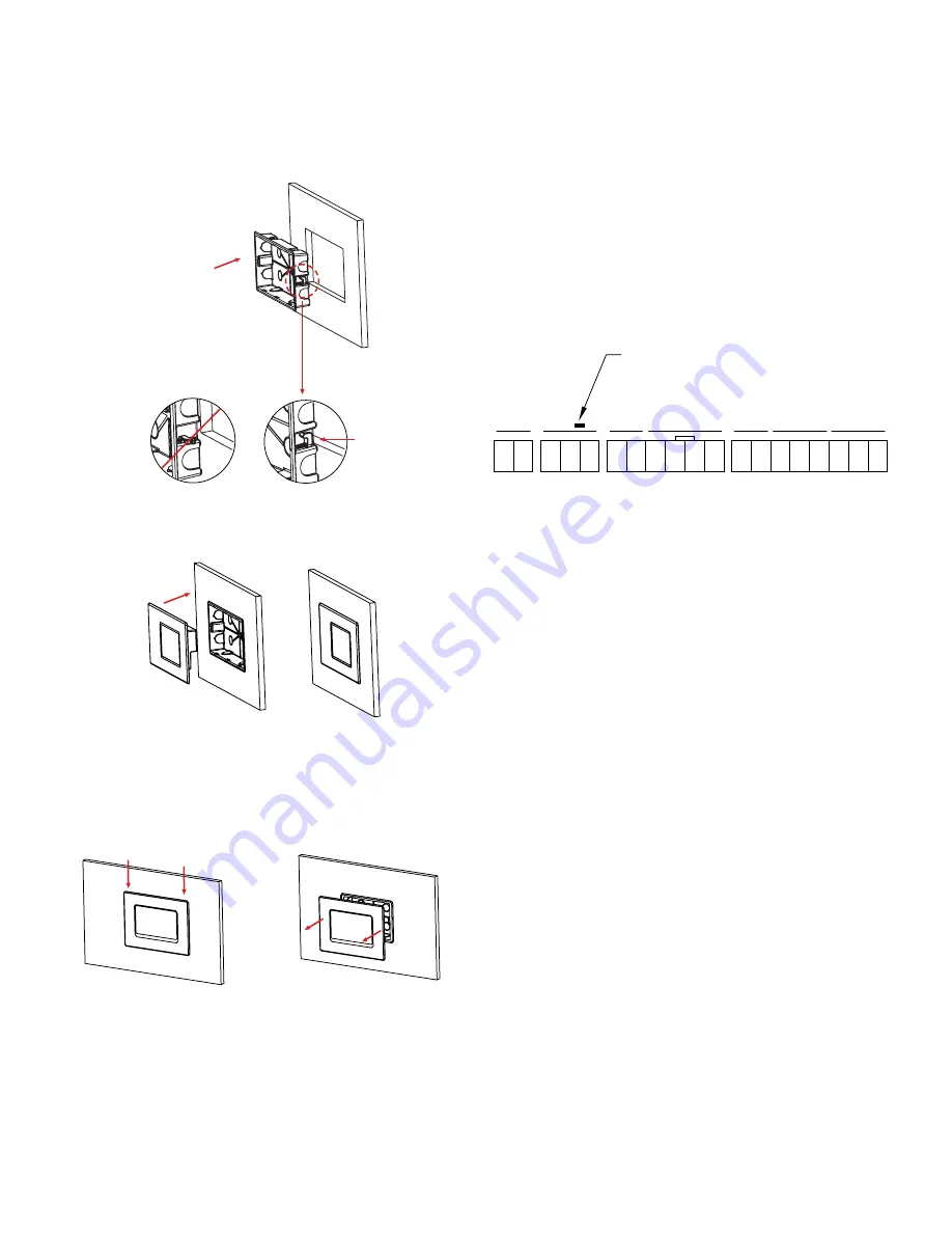
2.0 MOUNTING
The Series RSMC is designed to be mounted flush into a wall or panel. Use the
included cardboard cut-out as a template to ensure proper wall cut-out dimensions.
After cutting a 4.21˝ x 7.91˝ hole (107 mm x 201 mm), push the junction box into the
wall orienting the 2 screw tabs upward and push the box into the cutout, as shown in
Figure 1. Next use a screwdriver to secure the 2 screw tab wall locks. After the junction
box is installed firmly into the wall or panel, carefully push the RSMC into the junction
box as shown in Figure 2 below (after wiring the terminal block). The rear housing will
snap into the junction box.
The front panel can be removed from the junction box by pushing downwards on the
top lip of the bezel. The downward force will release the snap clips, then the front panel
can be pulled out as shown in Figure 3 below.
Figure 1
1
2
3
4
5
6
7
8
9
10
11
12
13
14
15
16
17
18
19
POWER
RELA
Y/DIG.
DIG.
RS48
5
AN. OUTPUT
CURRENT
VO
LT
AG
E
-
+
NO
COMMO
N
NC
DIG. INPU
T
DIG. COMMO
N
B+
A-
TERM. RESIST
.
RS485 GN
D
OUTPUT
+
OUTPUT
GN
D
UI1 4-20 mA
UI2 4-20 mA
INPU
T
GN
D
UI1 0-10
V
UI2 0-10
V
INPU
T
GN
D
OUTPUT
FACTORY/PASSWORD
RESET BUTTON
INPU
T
INPUTS
INPUTS
OK
Figure 2


