PAGE 12
BULLETIN F-56
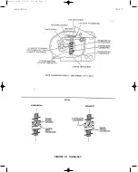
3. For access to cam and loosening of cam mechanism, perform the following steps.
1) Rotate access cover (and gasket). Refer to Page 1.
2) If present, remove extension spring from spring anchor; then remove screw, washer, and
anchor. See Figure 2-1.
3) Slightly loosen hex nut or standoff so input shaft is free to turn without turning cam (7/16˝
socket needed).
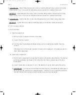
4. If it is necessary to use other side of cam: remove nut or standoff, turn cam over, and install the
washer and standoff; do not tighten Standoff. Cam must be free to rotate.
5. Index cam as follows:
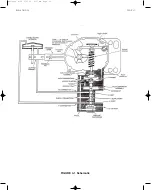
For the following steps, refer to Figure 2-4 when using the A side of a cam or to Figure 2-5 when
using the B side of a cam. Detail A shows cam nomenclature.
1) Turn on the supply pressure.
2) Ensure that valve actuator is seated in the position desired with no Positioner input signal. If
it is not, loosen fine zero locknut and adjust the fine zero thumbwheel as needed; tighten fine
zero locknut.
3) Carefully align minimum input index line with center of cam follower bearing pin and tighten
cam locknut or standoff to 70-75 in./lbs torque.
4) If removed in step 3 on the preceding page, reinstall, spring anchor and extension spring.
5) Loosely reinstall the access cover (and gasket) to prevent both inadvertent damage to
Positioner components and introduction of dirt and other foreign matter into the Positioner.
6) Turn off supply pressure.
6. Proceed to section 3 Calibration.
Bulletin F-56 6/27/05 9:37 AM Page 12


