background image

- 5 - 

9.


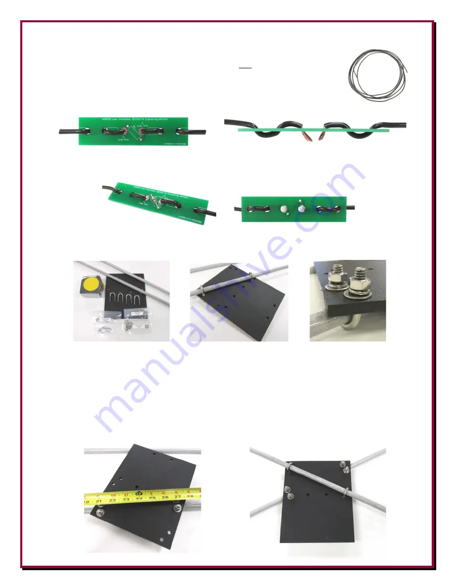
Using the 13 feet of the black antenna wire, cut it in half to make 2 wires the 
same length. Strip approximately 1/4” to 3/8” off one end of each wire. 

 
10.


Route one wire through the resistor PCB as shown and trim as needed. Route 
the 

second

 wire through the resistor PCB as shown, solder the two ends in 

place and trim as needed. 


11.


Install the 680 ohm 1/4 watt resistor in the resistor PCB, solder in place and trim as needed. 


12.


Assemble one 1/2” OD cross fiberglass rod to the black starboard center board as shown. Once 
the U-bolts are installed, just snug, do not tighten them at this time. 


13.


To center up the fiberglass rod, use a tape measure and measure one half the length of the rod 
from the end of the fiberglass rod to the center of the starboard center board. Once the rod is 
centered, tighten the U-bolt hardware for that rod. Do not over tighten. The distance from the 
end of one rod to the U-bolt hardware is 21 inches as shown. From the other end of hat same 
rod, it should also be 21 inches to the U-bolt hardware on that side as well. Evenly tighten the u-
bolts in place. 

 
14.


Repeat for the second fiberglass rod on the other side of the starboard center as shown. 


Summary of Contents for DXE-NOISELOOP-INS Series

Page 1: ...Kit DXE NOISELOOP DXE NOISELOOP INS Series Rev 0a DX Engineering 2021 1200 Southeast Ave Tallmadge OH 44278 USA Phone 800 777 0703 Tech Support and International 330 572 3200 Fax 330 572 3279 E mail D...

Page 2: ...loop was born Traditionally Flags are large and designed for stationary use whereas the idea for this was to design a Portable Flag The Portable Flag was designed to be the largest possible to maximiz...

Page 3: ...ing 2 Hex Nut Stainless Steel 1 4 20 2 Flat Washer Stainless Steel 1 4 2 Split Washer Stainless Steel 1 4 1 Resistor 680 ohm 1 4 w 1 Shrink Tube with Adhesive 3 8 OD 1 5 Length 1 Starboard Center Blac...

Page 4: ...on tubes in the core allowing approximately 1 2 hanging out Make 12 turns through the Teflon tubes in the core Keep the wire snug One turn is once through each side of the core Using the red magnet wi...

Page 5: ...int PCB and run the wires through the feed point PCB as shown Note colors of the wires in photo The green wires secondary connect to the Loop Wire holes the red wires primary connect to the holes near...

Page 6: ...arboard center board as shown Once the U bolts are installed just snug do not tighten them at this time 13 To center up the fiberglass rod use a tape measure and measure one half the length of the rod...

Page 7: ...he antenna wire centered front to back Tighten the element clamps in place 16 Install one p clamp wire guide flat washer and Nyloc hex nut onto each of the element stud clamps as shown Tighten in plac...

Page 8: ...PCB 19 Prepare the coaxial cable with BNC connector as shown below Cut approximately one inch of the black insulation off of the coax end Take care not to cut or nick the shield You want to separate...

Page 9: ...s in place Do not over tighten 21 Route the coaxial cable as shown and use a zip tie to hold it in place Do not over tighten the zip tie you just want it snug 22 Use an antenna analyzer to verify the...

Page 10: ...nal 9 volt battery has BNC connectors for Input and Output Easy to use slide switches and a power on LED when the Pre Amp is turned on Selectable attenuations levels of 10 db 20 db and 30 db when both...

Page 11: ...io attached and tuned to the HF band desired rotate the antenna until there is a null not the peak in the selected desired noise frequency Moving 90 degrees away from your current position then turnin...

Page 12: ...not extend to any products or parts thereof which have been subjected to any misuse or neglect damaged by accident rendered defective by reason of improper installation damaged from severe weather inc...

Reviews: