- 7 -
18.
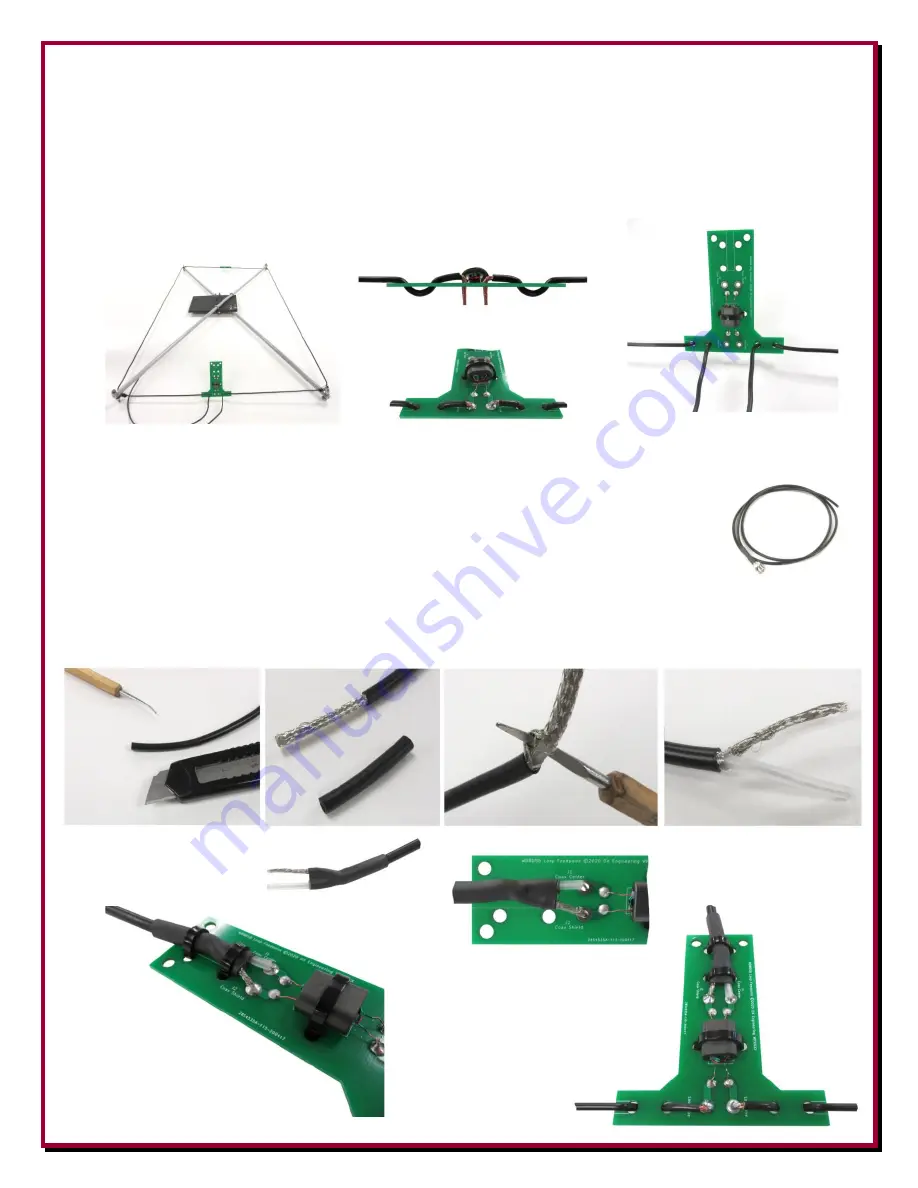
Use the feed point PCB on the other side of the loop and route the antenna wires through the
guides and then through the feed point PCB
keeping the feed point PCB centered between the
rods
.
Ensure the resistor PCB is still also centered
. Snug up the wires and make a small mark
on each wire just above where it passes through the PCB eyelets that will be soldered. Remove
the wires from the feed point PCB, trim the wire lengths and insulation back 1/4” to 3/8” on the
ends. Re-route the wire through the feed point PCB
ensuring all is centered and snug
. Solder
the two wires on the feed point PCB.
19.
Prepare the coaxial cable with BNC connector as shown below. Cut approximately one inch of
the black insulation off of the coax end. Take care not to cut or nick the shield.
You want to separate the shield and center insulation as shown using a soldering
pick or other small tool (small Phillips head screwdriver works good). Trim
about 1/2” of the center insulation from the center coax conductor. Take care
not to cut or nick the center conductor strands. Install the shrink tube with
adhesive near the ends of the prepped coax using a heat gun or other hot air
source to shrink the tube as shown. Insert the shield and the center conductor of the coax
assembly through the feed point PCB and solder in place. Use two zip ties to snugly hold the
coax cable against the feed point PCB as shown.


