114
10. Part Replacement Guide
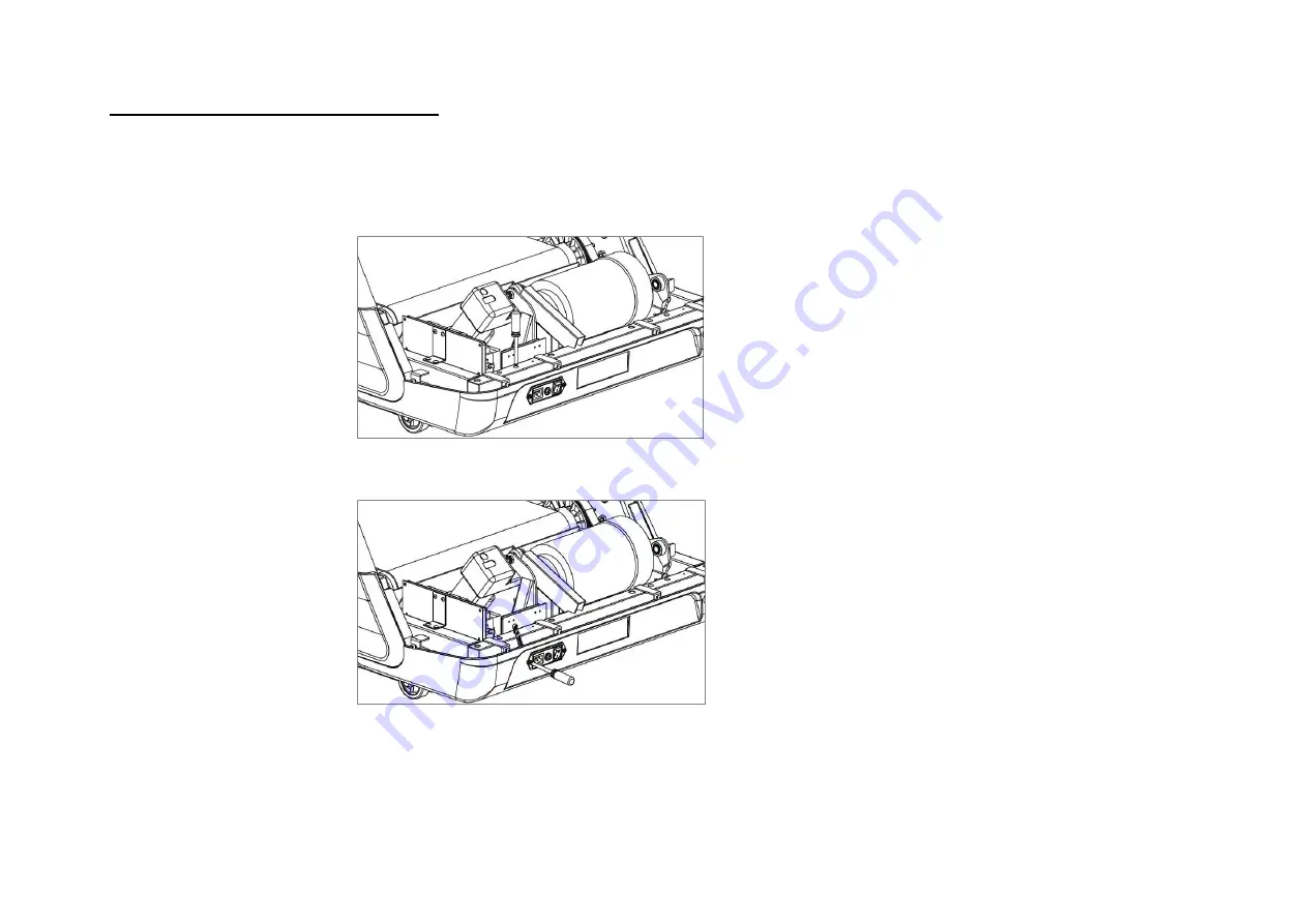
10.1.4 A.C. Input Module Replacement
1) Remove the motor cover.
2) Remove the A/C power switch ground wire using a screwdriver as shown in Figure 6.4.1.
Figure 6.4.1
3) Remove the A/C power switch module and switchboard as shown in Figure 6.4.2.
Figure 6.4.2
4) Replace the parts in the order of removal.
Summary of Contents for 78556
Page 4: ...4 2 Elektronische Bauteile Obere Kontrollelemente Computer Lüfter Sicherheits clip ...
Page 8: ...8 4 Grundlegende Verbindungen Layout der Steuerplatine VFD015TM12A ...
Page 16: ...16 6 Fehlermeldungen Fehlerbehebung Schaltplan engl ...
Page 47: ...47 9 Installation des Steigungsmotors 9 1 Seriennummer ...
Page 65: ...65 2 Electronic Parts Upper Controls Console Cooling Fan Safety key ...
Page 66: ...66 2 Electronic Parts Lower Controls and Drive A C Motor Incline Motor Inverter ...
Page 69: ...69 4 Basic Connections and Wiring Driver PCB Board Layout VFD015TM12A ...
Page 77: ...77 6 Error Messages Troubleshooting Circuit diagram ...
Page 95: ...95 6 Error Messages Troubleshooting Name rename BT device ...
Page 108: ...108 9 Installation of the Incline Motor 9 1 Serial Number Location ...


